Maker Pro
Maker Pro

SMPS feedback loop injection resistor?

eem2am

Aug 3, 2009
429
Joined
Aug 3, 2009
Messages
429
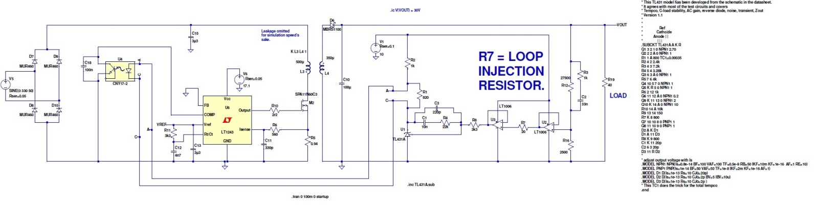
The following is a Flyback SMPS.

Is R7 a good place for a loop injection resistor for the purpose of feedback loop measurement?

(Flyback = CCM, continous, 97khz, 22.5w, vout=30v, Vin = 230VAC)

The whole error amplifier network has been designed with two extra opamps (U2 & U3) “encasing” a loop injection resistor (R7), which is to be used for loop test signal injection, for establishing the gain and phase margins of this SMPS.
A frequency analyser (eg AP300) would be used for the loop injection, via a coupling transformer, as follows
http://www.ridleyengineering.com/loop-stability-requirements.html?showall=&limitstart=

Attached is the schematic in pdf and jpeg, as well as the LTspice simulation.

2exn88l.jpg
 

Attachments

  • Flyback _TL431_bias_type3_.txt
    10.5 KB · Views: 125
  • Flyback _TL431_bias_type3_.pdf
    19.6 KB · Views: 196

Arouse1973

Adam
Dec 18, 2013
5,178
Joined
Dec 18, 2013
Messages
5,178
Don't see the purpose of the 20R from low impedance buffer to high impedance input. Buffer with short across out to in not good in some cases.
Adam
 

eem2am

Aug 3, 2009
429
Joined
Aug 3, 2009
Messages
429
That 20R is the injection resistor, the secondary of the injection transformer will go across it.......this resistor must see low impedance looking one way, and high impedance looking the other.....so that is provided by the two opamps as they are positioned.

I am a bit worried if it matters that the output impedance of the opamp will be more than the 20R of the injection resistor...if so, I will have to up the value of the injection resistor.
The LT1006 output resistance is around 220R
http://cds.linear.com/docs/en/datasheet/1006fa.pdf

..I think I need to make the injection resistor at least 5K.?

The injection signal will be swept in frequency by the AP300 frequency analyser and the voltage at each end of the 20R resistor will be compared by the frequency analyser to produce the power supply bode plots...

AP300 use ..
 
Last edited:

Arouse1973

Adam
Dec 18, 2013
5,178
Joined
Dec 18, 2013
Messages
5,178
Ah I see.
Well the output impedance for the buffer I think is going to be the Ro of the op-amp itself, which is going to be quite low. Not checked the device yet. I'll look later and let you know.
Thanks
Adam
 

eem2am

Aug 3, 2009
429
Joined
Aug 3, 2009
Messages
429
I actually do think my top post shows a good place for the injection resistor, and believe this is a new, superb, revolutionary method for successfully measuring stability on such a type of SMPS.....Do you agree with this?.....

-so, the attached is an adjustment of the above schematic to prevent overshoot on startup by adding R3 and C2....

The following is a flyback with vin = 250V, VOUT = 30V, pout=22.5w, fsw=97khz, CCM, current mode.
As discussed, the only way to measure an effective feedback loop gain/phase plot is to put the two opamp buffers (U3 and U2) either side of the feedback loop injection resistor, R7.
Do you agree? (schematic attached)
The “standard” position for the loop injection resistor is sometimes seen in series with the upper divider resistor, R12, however, if the Opamps were not added, R12 would need an RC circuit across it to reduce vout overshoot at start-up, and the capacitance of the “C” of this “RC” circuit means that the upper feedback divider impedance is too low to allow series insertion of the loop injection resistor there.
(The loop injection resistor must “see” low impedance “looking out” from one of its terminals, and high impedance “looking out” from its other terminal…..thus the two opamps)
When the opamps are used, the RC circuit of R3 and C2 prevent overshoot at start-up.
Do you agree that this method is the best way to get a bona fide gain/phase plot of the SMPS?……when the measurement has been taken during testing, the two opamps and loop injection resistor will simply remain fitted when shipped to customer, as they do no harm.
Here is the schematic and LT spice simulation with loop injection going on.
The feedback loop signals (‘loop_in’ & ‘loop_out’) appear to show a phase margin of 45 degrees at the crossover frequency.
(bode plots measured eg with AP300 frequency analyser)
 

Attachments

  • Flyback _TL431_bias_type3_opamp.pdf
    22.5 KB · Views: 142
  • Feedback loop signals.jpg
    Feedback loop signals.jpg
    64.4 KB · Views: 198
  • Flyback _TL431_bias_type3_opamps.txt
    11.8 KB · Views: 109
Last edited:

Arouse1973

Adam
Dec 18, 2013
5,178
Joined
Dec 18, 2013
Messages
5,178
You crack me up. I love reading your posts, your so much like me. In your face lol. Your posts are quite complex and frequent. Give me time and I will respond to all.
Adam
 

Arouse1973

Adam
Dec 18, 2013
5,178
Joined
Dec 18, 2013
Messages
5,178
The output versus load is not linear so that means the resistance can't be easily calculated. Have a look on the data sheet and use the graph to help you work it out. It's going to be quite high for this op-amp can only supply 10mA
Thanks
Adam
 

eem2am

Aug 3, 2009
429
Joined
Aug 3, 2009
Messages
429
http://cds.linear.com/docs/en/datasheet/1006fa.pdf

yes I agree, the Zout of the LT1006 opamp varies between 200R to about 350R.
I don't think this matters though.
All that matters is that the resistance looking "back" from the injection resistor is much less than the resistance "seen" looking "forward " from the injection resistor...and that is granted, so its ok?.

The standard place for the injection resistor is above the upper feedback divider resistor, and as such ,it would "see" Cout...whose impedance varies considerably with frequency, but again this does not matter.
 
Top