Maker Pro
Maker Pro

Soldering High Amperage Transistors

fatman57

May 27, 2013
110
Joined
May 27, 2013
Messages
110
I am planning to build a controller that needs to cope with around 36 amps continuously. I am trying to find a good way of soldering transistor pins to a large wire. Does anyone have any tips?

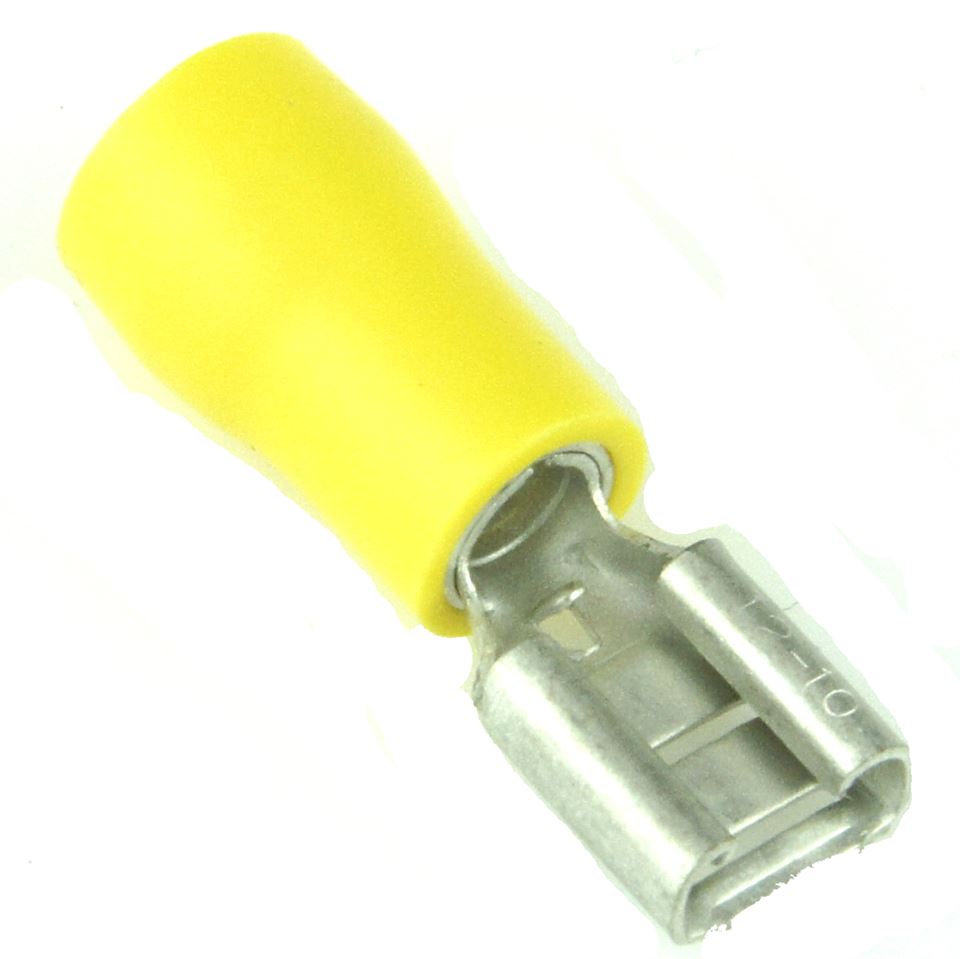
Please see image at the below:
largeWireSolder_2.jpg


A bit messy but similar to what I was thinking, on the left side would be a crimped terminal that screws onto the bolt, then copper wire is wrapped around the bolt (and tightened) with the other end of the cable soldered to the transistor.

Some of my issues are:
- How can the pins of a resistor stand up to the current demands when I require a cable so large to carry it?
- I think the soldered part looks messy, I also worry that the contact area between the pin and wire will not be enough to carry the current.

Any help or advice would be much appreciated.
 

Harald Kapp

Moderator
Moderator
Nov 17, 2011
13,722
Joined
Nov 17, 2011
Messages
13,722
How can the pins of a resistor stand up to the current demands when I require a cable so large to carry it?
That resistor has 3.3kΩ. Not much current will flow through it.
I think the soldered part looks messy,
Definitely!
I also worry that the contact area between the pin and wire will not be enough to carry the current.
As you are obviously not using a PCB, I suggest you bend up the transistor pin at a right angle, then wrap the wire around the pin and solder. With wire this thick you will need a lot of thermal energy to make a good solder joint. You risk overheating the transistor. You should at least hold the transistor pin with good pliers near to the transistor case and you should solder at the far end of the pin. Both to keep the transistor as cool as possible during soldering.

As a better method I recommend to solder the transistor onto a PCB and from there to suitable screw terminals. Then screw the wire into the screw terminals.
 

duke37

Jan 9, 2011
5,364
Joined
Jan 9, 2011
Messages
5,364
I would suggest bending up the current carrying pins and solder them to some sheet copper. Connect your fat wire to the copper sheet first. Cut the copper to give strips which can be bent from each other to improve the heat transfer.

The collector will be connected to the tag and a heat sink can be added there.
 

fatman57

May 27, 2013
110
Joined
May 27, 2013
Messages
110
That resistor has 3.3kΩ. Not much current will flow through it.

Apologies as that was a typo - I meant 'Transistor' :(

I am using a PCB, but I will find it hard to get a PCB that can withstand 36 amps. Hence my need for extra wiring. I agree with screw terminals, but again how do I transfer the current from the screw terminal to the transistor? The wire I am thinking of using is about 6mm2, around 4.3mm diameter. Apparently that size should be able to deal with around 50amps, so this is my safety factor. 36 amps is the maximum expected to be drawn. My only issue is soldering the wire to the transistor pins. Their relative sizes was quite a lot, and enough to be questioned - I have no idea how these things don't blow.

Just to note the original picture is not my work but a similar example I found on the internet.

Thanks for all the soldering tips - they really will come in handy!
 
Last edited:

fatman57

May 27, 2013
110
Joined
May 27, 2013
Messages
110
I would suggest bending up the current carrying pins and solder them to some sheet copper. Connect your fat wire to the copper sheet first. Cut the copper to give strips which can be bent from each other to improve the heat transfer.

The collector will be connected to the tag and a heat sink can be added there.

I have thought about sheet copper, indeed I think the finish might be better. My difficulty in manufacture is cutting the sheet to size as it might end up being quite thick.
 
Last edited:

duke37

Jan 9, 2011
5,364
Joined
Jan 9, 2011
Messages
5,364
You
I have thought about sheet copper, indeed I think the finish might be better. My difficulty in manufacture is cutting the sheet to size as it might end up being quite thick.
You want thick copper to conduct the heat. I have used central heating copper pipe, slit down the side and opened up. A job for my big hammer.:) I have also used copper sheet from a leaking hot water cylinder, less thumping necessary.
The transistor tag which is bolted down is connected to the collector and where the copper sheet can be bolted.
A short coil around the emitter and the wire will enable a solder connection to be made speedily.
 

fatman57

May 27, 2013
110
Joined
May 27, 2013
Messages
110
You

You want thick copper to conduct the heat. I have used central heating copper pipe, slit down the side and opened up. A job for my big hammer.:) I have also used copper sheet from a leaking hot water cylinder, less thumping necessary.
The transistor tag which is bolted down is connected to the collector and where the copper sheet can be bolted.
A short coil around the emitter and the wire will enable a solder connection to be made speedily.

That sounds similar to what Harald proposed, do you have any visual examples?

Apparently 1mm diameter solid copper cable can take 16amps, so in theory a 1mm thick sheet that is 2mm wide can take 32 amps. If true I could use this for my sizing.
 

duke37

Jan 9, 2011
5,364
Joined
Jan 9, 2011
Messages
5,364
I do not know on what you base the current limit of a wire. A watt or two dissipation should not be a problem in free air. Make sure the transistor is heat sinked properly.
I do not have pictures of my bodging.
 

fatman57

May 27, 2013
110
Joined
May 27, 2013
Messages
110
I do not know on what you base the current limit of a wire. A watt or two dissipation should not be a problem in free air. Make sure the transistor is heat sinked properly.
I do not have pictures of my bodging.

What about a blue terminal crimp (max of around 30amps) crimped onto the transistor pin and then connected to the wire?

Total system will be 36amps, but this will be split between 2 transistors which means about 15amps each max, so to make a good finish I could try using terminal clamps (crimp and solder maybe). BUT - again, how does such thin metal deal with such high amperages! Yellow terminal crimp is supposed to work up to 50amps apparently, but is nowhere near as thick as the 4mm diameter wire it is supposed to crimp to...

Or maybe even a yellow female spade terminal crimp as illustrated below:
0029746_yellow-pre-half-insulated-crimp-14-female-spade-terminals-50pcs.jpeg


Slide the spade on the transistor pin, make this tight with pliers then solder. Then simply crimp the cable end as normal?
 
Last edited:

fatman57

May 27, 2013
110
Joined
May 27, 2013
Messages
110
I have decided to revise my approach, and one option was to simply clamp the transistor pins. I have made a prototype to see how this could work, please see samples below. Unfortunately I haven't properly figured out close up shots on my camera, so please accept my apologies:

IMG_081112292.jpg

IMG_0812ba253.jpg

IMG_0813c1a05.jpg

IMG_08190be05.jpg

IMG_0820dfac2.jpg


It is only a prototype, on the bottom of course I would remove the copper on the board between the bolts. Rather than have metal washers on the top I could use nylon to isolate the bolts, but at the bottom I am not too sure as I would like to have both sides of the transistor pin in contact. I could also add solder if I use brass washers for example but I am not sure this is necessary. I plan to solder the transistor pin to the board where it comes through at the bottom.

Contact length at a conservative measurement is around 3mm, will this be enough? Also, is this whole approach not going to work - is clamping a bad idea? Will it need solder for example?

Much obliged for any feedback.
 

duke37

Jan 9, 2011
5,364
Joined
Jan 9, 2011
Messages
5,364
The transistor is cooled by the collector/drain tag connected to the middle pin.
The transistor leads are cooled by soldering them to substantial copper tracks. Soldering will be better than just clamping. Plastic/nylon will not help.
 

fatman57

May 27, 2013
110
Joined
May 27, 2013
Messages
110
The transistor is cooled by the collector/drain tag connected to the middle pin.
The transistor leads are cooled by soldering them to substantial copper tracks. Soldering will be better than just clamping. Plastic/nylon will not help.

Ok thanks. The nylon is just to isolate at the top - I was thinking more if the heatsink were to get knocked or something. I am trying to find an interface between the transistor pins and bolts, as with bolts I can easily use plates.

I could try brass washers, as these apparently are about the same as copper to solder to. I am slightly worried about any sheer forces (I have no idea how solder puts up with sheer) between the washers. I am trying to also make this easy to work with.
 

twister

Feb 12, 2012
172
Joined
Feb 12, 2012
Messages
172
You can use short wires of stranded wire , say 16 or 20 ga.,to hook to your large buss wire. I have seen this used in my inverter that are carrying maybe 20 amps. If you measure the resistance of a short piece of 16 ga. wire you will understand that the resistance is VERY LOW. That is the reason that it can carry a very large current with little loss of voltage. Look at the size of those terminals on the transistor, and they easily carry 15 amps!
I tried to post a photo of my solar panel voltage regulator but could not for some reason.
 

fatman57

May 27, 2013
110
Joined
May 27, 2013
Messages
110
You can use short wires of stranded wire , say 16 or 20 ga.,to hook to your large buss wire. I have seen this used in my inverter that are carrying maybe 20 amps. If you measure the resistance of a short piece of 16 ga. wire you will understand that the resistance is VERY LOW. That is the reason that it can carry a very large current with little loss of voltage. Look at the size of those terminals on the transistor, and they easily carry 15 amps!
I tried to post a photo of my solar panel voltage regulator but could not for some reason.

Thanks!

Yes that makes sense, the table below, even though maybe not the best source, defines a difference between using cable for short lengths and 'chassis wiring' :
http://www.powerstream.com/Wire_Size.htm

I guess this explains why the transistor pins can be so short. Rather than increase the length of the connection I think I will stick to trying to solder directly to the bolt. I am also learning, so when (if ever!) assembled I can measure some temps while it is running and see how it fares.
 

ProtofabTT

Jun 7, 2017
5
Joined
Jun 7, 2017
Messages
5
I have a project using IRFP3206 NFETs delivering upwards of 600A capacitive pulses, using 1 oz PCB copper. The trick is to augment the copper traces with desoldering braid or # 18AWG wiring. The total run is about 3". Without the augmentation the PCB traces will bake off and delaminate and destroy the PCB. Possibly desoldering the transistors as well. The pulsed power is transferred via a pair of PCB mounted, 2 mΩ contact resistance, 80A, truck relays as it must be switched. A single relay only lasts a month before sticking as it runs up to 120°C at the internal contacts. Dual relays hold the temperature to 85°C at the contacts. I sampled the temperatures with an E8 FLIR camera via a window cut into the relay body.

The other challenge I had to solve was the inductance of the out going cables and how to move 600A off a PCB. That requires 4 x #14 AWG OFC audio grade cabling in parallel and 1/4" spade terminals crimped and soldered. I measure the finished cabling & connectrs with a milliohmeter accurate to 0.1 mΩ. I still have to snub/flywheel up to 20W of backemf from the pulsed switching but that's handled by a 2KA pulse diode now.

The 3 'cabling tops out at about a 30°C heating delta over ambient.
 

fatman57

May 27, 2013
110
Joined
May 27, 2013
Messages
110
So this is the latest, I found spade terminals for PCB boards and it looked like it could work, please see images below:

IMG_0883.jpg

IMG_0884.jpg

IMG_0885.jpg

IMG_0888.jpg


The gives me a much greater contact area of nearly 1cm in length (compared to 3mm), it should also be easier to manufacture. At the moment I simply bent the terminal but I will look into the pre-made ones.

My only concern here is that the material of this item is zinc - which is apparently OK but not the best to solder to. Can anyone offer any advice on this issue? There are brass versions of this but I fear they might be larger and not fit my project as well but I will look into it. Is zinc ok to solder to?
 

fatman57

May 27, 2013
110
Joined
May 27, 2013
Messages
110
I have a project using IRFP3206 NFETs delivering upwards of 600A capacitive pulses, using 1 oz PCB copper. The trick is to augment the copper traces with desoldering braid or # 18AWG wiring. The total run is about 3". Without the augmentation the PCB traces will bake off and delaminate and destroy the PCB. Possibly desoldering the transistors as well. The pulsed power is transferred via a pair of PCB mounted, 2 mΩ contact resistance, 80A, truck relays as it must be switched. A single relay only lasts a month before sticking as it runs up to 120°C at the internal contacts. Dual relays hold the temperature to 85°C at the contacts. I sampled the temperatures with an E8 FLIR camera via a window cut into the relay body.

The other challenge I had to solve was the inductance of the out going cables and how to move 600A off a PCB. That requires 4 x #14 AWG OFC audio grade cabling in parallel and 1/4" spade terminals crimped and soldered. I measure the finished cabling & connectrs with a milliohmeter accurate to 0.1 mΩ. I still have to snub/flywheel up to 20W of backemf from the pulsed switching but that's handled by a 2KA pulse diode now.

The 3 'cabling tops out at about a 30°C heating delta over ambient.
Thanks! Always like hearing what other people are going through, also some great advice and tips. I am always learning of course so these types of things really help.

600A is one **** of a lot, I wouldn't even dare approach that project! 30A was bad enough for me. 18AWG is apparently only 1mm, this is what I usually used but for this project I though it would need to handle much more. This could be my inexperience making me over engineer a solution - will 18AWG take 600A? I presume only because it is pulsed...?
 

duke37

Jan 9, 2011
5,364
Joined
Jan 9, 2011
Messages
5,364
Zinc is difficult to solder and is soft to but what part is made of zinc? Iron is galvenised for roofs and zinc is sometimes used a a substitute for lead flashing.
The parts you show in the pictures appear to be either copper or brass which are tin plated and should be easy to solder given sufficient heat.
 

fatman57

May 27, 2013
110
Joined
May 27, 2013
Messages
110
Zinc is difficult to solder and is soft to but what part is made of zinc? Iron is galvenised for roofs and zinc is sometimes used a a substitute for lead flashing.
The parts you show in the pictures appear to be either copper or brass which are tin plated and should be easy to solder given sufficient heat.

It says Zinc plated, but I gave it a good scratch and didn't see any colour beneath it :(
 
Top