Maker Pro
Maker Pro

[Solved] Trying to drive a MOSFET with a potentiometer leads to dead short

Photomultiplier

Nov 22, 2022
18
Joined
Nov 22, 2022
Messages
18
Hello,
I must be making a very basic mistake, or the MOSFET must be broken. In either case, here's the schematic.
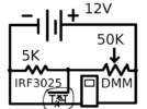
heatsink-tester.png

The purpose of this circuit is to test a heatsink's power dissipation capabilities. The IRF3025 is, of course, on top of the heatsink.

Every time I connect up the - battery terminal to the drain, which is the last I connect, I get what appears to be a dead short. I don't want to leave the circuit on long enough to see just how much current flows, because the wire tip lights up white hot with the spark.
I've tried turning the potentiometer down to 100ohms, up to 50Kohms, and I also tried just connecting the drain to the negative terminal, not the 5Kohm resistor. Nothing worked.
The MOSFET's resistance is 10.4Kohms source to drain and 3.4Mohms drain to source. I used one of those cheap TC-1 multi-function testers, and it says everything's fine with the MOSFET. I also used it to verify that the MOSFET really is connected up the way I think that it is.

What I want is for the MOSFET to act as a variable resistor.

Anyone know what's going on and how to solve it?

Thanks!
 

Attachments

  • heatsink-tester.png
    heatsink-tester.png
    17 KB · Views: 0

Externet

Aug 24, 2009
891
Joined
Aug 24, 2009
Messages
891
What is the meaning of 'dead short' for you ?
What scale is your DMM set at ?
 

danadak

Feb 19, 2021
768
Joined
Feb 19, 2021
Messages
768
Your schematic shows source and drain swapped, drain should be connected to
positive V circuit side and source to negative circuit side.

1686016068099.png

1686016182945.png


Regards, Dana.
 
Last edited:

crutschow

May 7, 2021
850
Joined
May 7, 2021
Messages
850
I must be making a very basic mistake
You are.
As danadak noted, the MOSFET is connected backwards.
Note the direction of the parasitic substrate diode between source and drain that all MOSFETs have.
It's forward biased in you diagram, so provides the near dead short you noted.
 

Photomultiplier

Nov 22, 2022
18
Joined
Nov 22, 2022
Messages
18
You are.
As danadak noted, the MOSFET is connected backwards.
Note the direction of the parasitic substrate diode between source and drain that all MOSFETs have.
It's forward biased in you diagram, so provides the near dead short you noted.
Ah! Here I thought source was positive! I'm too used to thinking in terms of VCC being positive.
Thanks!
 

danadak

Feb 19, 2021
768
Joined
Feb 19, 2021
Messages
768
There are MOSFETs that are symmetrical with respect to Source and Drain,
eg. those connections can be interchanged. But asymmetric vastly more prevalent
in practice and designs.


Regards, Dana.
 

Photomultiplier

Nov 22, 2022
18
Joined
Nov 22, 2022
Messages
18
There are MOSFETs that are symmetrical with respect to Source and Drain,
eg. those connections can be interchanged. But asymmetric vastly more prevalent
in practice and designs.


Regards, Dana.
How do you know when you are looking at an asymmetric one?
 

crutschow

May 7, 2021
850
Joined
May 7, 2021
Messages
850
There are MOSFETs that are symmetrical with respect to Source and Drain,
I know of no discrete MOSFET that has that characteristic without a substrate diode requiring a connection (normally to the source). There may be some (I know of none) that add an external connection for the substrate diode but it must be biased with an appropriate voltage to keep it from ever being forward biased.
 
Last edited:

danadak

Feb 19, 2021
768
Joined
Feb 19, 2021
Messages
768
I know of no discrete MOSFET that has that characteristic without a substrate diode requiring a connection (normally to the source). There may be some (I know of none) that add an external connection for the substrate diode but it must be biased with an appropriate voltage to keep it from ever being forward biased.
I only know of the duals that when series connected negate the body diode effect.

And of course this :


Regards, Dana.
 

Delta Prime

Jul 29, 2020
1,968
Joined
Jul 29, 2020
Messages
1,968
How do you know when you are looking at an asymmetric one?
I know over 14 different schematic symbols for mosfets and half of those schematic symbols mean the same thing! look up IEEE mosfet standard symbols.

photo_1686135336636.pngphoto_1686135187050.pngphoto_1686135053436.pngphoto_1686134850810.png
 

Attachments

  • Design_and_Fabrication_of_Asymmetric_MOSFETs_Using.pdf
    1 MB · Views: 1

Harald Kapp

Moderator
Moderator
Nov 17, 2011
13,724
Joined
Nov 17, 2011
Messages
13,724
I know over 14 different schematic symbols for mosfets
The variance in symbols used for drawing MOSFETs is indeed misleading to the novice.
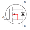
Looking at the op's question, he uses an IRF3025. The datasheet of his MOSFET shows this symbol:
1686138166003.png
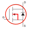
S, G and D are clearly labeled. Also clearly shown is the body diode between drain and source. The backgate (B) os not explicitly shown. As this symbol indicates, the connection is internal to the component (see red lines) and not accessible from the outside:
1686138320590.png
This symbol also makes it unmistakeably clear why the op measures a near short-circuit due to D and S being swapped and thus the diode being conductive.
 

Delta Prime

Jul 29, 2020
1,968
Joined
Jul 29, 2020
Messages
1,968
I totally agree.
(see red lines)
I only see one red line (trick question got you!)
You see the red circle everything is internal except for what is protruding out of the red circle indicated S,D,G.
To the Thread Starter.
May serendipity be your travel companion on this journey you have embarked upon.

photo_1686162414679.png
 
Top