Maker Pro
Maker Pro

Sony Receiver STR - DA555ES Displays "protection fan" when turned on.

Rick79

Nov 26, 2014
283
Joined
Nov 26, 2014
Messages
283
20141211_025815.jpg 20141211_025725.jpg 20141211_025601.jpg I noticed it has a blown fuse. I was wondering if it was ok to just replace this fuse to see if the fan turns on. Are there any components that have to be tested first?
 

Rick79

Nov 26, 2014
283
Joined
Nov 26, 2014
Messages
283
Ok. I tried replacing the fuse, but it just blew out. Is the fan causing this?
 

KrisBlueNZ

Sadly passed away in 2015
Nov 28, 2011
8,393
Joined
Nov 28, 2011
Messages
8,393
Maybe. And maybe it's the fan. You could try unplugging it, if it's unpluggable.

I'm just downloading the service manual now and will post again soon.
 

Rick79

Nov 26, 2014
283
Joined
Nov 26, 2014
Messages
283
Maybe. And maybe it's the fan. You could try unplugging it, if it's unpluggable.

I'm just downloading the service manual now and will post again soon.
Thanks. I unplugged the fan and tested the fan and it works so it must be something else right? Will I still be able to continue testing components on the board even though one of the fuses is blown?
 

KrisBlueNZ

Sadly passed away in 2015
Nov 28, 2011
8,393
Joined
Nov 28, 2011
Messages
8,393
Sorry for the slow reply!

If the fan works when powered externally, it's not likely to be the problem. There will be some tests you can do with the fuse blown, but we have to fix the problem that is causing the fuse to blow.

I've got the service manual but it's not complete. It does show the schematic of the fan circuit though.

The "protection fan" message on the display probably means that the firmware (the program that controls the unit) thinks it has detected some kind of problem with the fan, and is refusing to operate. The problem is that there doesn't seem to be any way for the firmware to detect whether the fan is running or not! The fan doesn't have any rotation feedback signal that the firmware could be checking, and its operating current cannot be detected either.

So I'm not clear on what the indication means. It could just mean that the +24V rail which supplies the fan is not present. In any case I think it will be best to start from the blown fuse, not from the diagnostic indication.

Can you give the circuit reference for the fuse that blows? For example, "FH901" etc.

Do you have a multimeter and do you know how to use it?
 

Rick79

Nov 26, 2014
283
Joined
Nov 26, 2014
Messages
283
Yes, i have a multimeter. The fuse holder has two numbers, one on each side. FH953 AND FH903
 

KrisBlueNZ

Sadly passed away in 2015
Nov 28, 2011
8,393
Joined
Nov 28, 2011
Messages
8,393
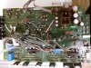
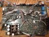
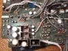
Right, the fuse clips are numbered separately in that design! So each fuse has two FH... numbers.

The fuse that clips into FH903 and FH953 is F953. Here are the relevant parts of the schematic.

271769 transformer.png
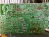
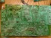
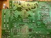
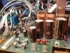
Here's the main power transformer. Mains voltage comes on on the right, into the primary winding, and the secondary windings on the left supply different parts of the circuit. The two connections I've marked with arrows and "D955" are relevant here; they feed into the marked wires in the next part of the circuit.


271769 power supply.png

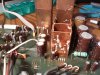
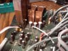
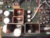
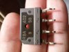
The wires at bottom right, marked with the arrow, come from the marked winding on the transformer. One of them passes through F953, the fuse that is blowing, and goes into D955, an RBA402 bridge rectifier, which converts the AC from the transformer into DC which is smoothed by C940 and feeds IC955 and IC902, two linear regulators that generate the +3.3V and +5V rails.

If F953 is blowing, the fault is most likely either D955 or one of those regulators. Can you remove D955 from the board (it has four leads) and test it using the diode test range on your multimeter, if it has one. Instructions for testing bridge rectifiers are all over the net. Here's a starting point: http://www.ehow.com/how_7918714_test-bridge-rectifier.html
 

Rick79

Nov 26, 2014
283
Joined
Nov 26, 2014
Messages
283
Ok. Looks like i might have to take everything apart because i dont have access to that part of the board even though the bottom cover is off. I'll try though
 

Rick79

Nov 26, 2014
283
Joined
Nov 26, 2014
Messages
283
I know the quality isnt that good plus its night time over here, but this is the board
 

Attachments

  • 20141213_002037.jpg
    20141213_002037.jpg
    210 KB · Views: 317
  • 20141213_001730.jpg
    20141213_001730.jpg
    249.5 KB · Views: 392
  • 20141213_001119.jpg
    20141213_001119.jpg
    255.1 KB · Views: 255
  • 20141213_000058.jpg
    20141213_000058.jpg
    251.7 KB · Views: 337
  • 20141212_235833.jpg
    20141212_235833.jpg
    225.6 KB · Views: 266
  • 20141213_000040.jpg
    20141213_000040.jpg
    235.4 KB · Views: 303
  • 20141212_235721.jpg
    20141212_235721.jpg
    190.5 KB · Views: 318
  • 20141212_235626.jpg
    20141212_235626.jpg
    190 KB · Views: 291
  • 20141212_235543.jpg
    20141212_235543.jpg
    192.4 KB · Views: 326
  • 20141212_235501.jpg
    20141212_235501.jpg
    172.3 KB · Views: 387
  • 20141212_232015.jpg
    20141212_232015.jpg
    145.5 KB · Views: 349
  • 20141212_231701.jpg
    20141212_231701.jpg
    144.2 KB · Views: 270

KrisBlueNZ

Sadly passed away in 2015
Nov 28, 2011
8,393
Joined
Nov 28, 2011
Messages
8,393
OK. Those pics are OK.

Now the bridge is removed, can you replace the fuse again and check that it doesn't blow. If it does, the problem is either a short I can't see, or those two small brown capacitors near the bridge marked ". C 103".

Assuming the fuse doesn't blow, can you power off and measure resistance across C960. That's the gold 4700 µF electrolytic behind the bridge rectifier position. I expect you'll see less than 1Ω resistance.

If that's the case, the fault is probably either IC902 or IC955. These are the three-terminal regulators on the tall copper heatsinks. I won't ask you to remove the heatsinks, but you could remove the regulators from the heatsinks and then remove them from the board. Start with IC902 because the mounting screw for IC955 is blocked by C961.

Remove the screw and desolder the pins, and the regulator should come out easily. Try not to get the white heatsink compond on your hands as it's apparently carcinogenic. Then re-measure resistance across C960. If it's no longer around 0Ω then IC902 was the problem. If it still is, then the problem is either IC955 (likely) or C960 itself (unlikely). So remove one of them and check again to find out.
 

Rick79

Nov 26, 2014
283
Joined
Nov 26, 2014
Messages
283
20141213_181922-1.jpg To power on the board, do i have to have to put everything back inside the stereo with everything connected like it was?

IC902 shows IC955 on the board. Is that a misprint?
 
Last edited:

Rick79

Nov 26, 2014
283
Joined
Nov 26, 2014
Messages
283
I need to go buy more fuses from the radioshack. Do you know if they have all these components you mentioned available in their stores? Im thinking i could just replace all those parts, but then again i wouldn't know exactly what was causing the fuse to blow. Do you think its possible even though i replace all those components it may still blow a fuse?
 

KrisBlueNZ

Sadly passed away in 2015
Nov 28, 2011
8,393
Joined
Nov 28, 2011
Messages
8,393
I hope this isn't too late!

Radio Shack will have the 7805 (IC955) but they won't have the BA033T (IC902). You could buy a 7805 because they're cheap.

They may have a 4700 µF 16V capacitor (C960) and you could buy one of those, but don't replace it until we know that the original is faulty because the original is a good Japanese one and the Radio Shack part will be some cheap Chinese piece of rubbish.

You could get a couple of the small capacitors (the ones marked "103") - any ceramic 0.01 µF ones will be OK.

If it's a hassle to put everything back together, don't refit the board, leave the bridge rectifier out, and measure resistance across C960. If you get less than 1Ω then the problem is one of the regulators (likely), or both regulators (less likely), or C960 itself (unlikely). If there's no short there, I guess it must be one or both of those small "103" capacitors.
 

Rick79

Nov 26, 2014
283
Joined
Nov 26, 2014
Messages
283
Sorry, i meant... Why does it say IC956 on the board when its supposed to be IC902 like the schematic shows?
 

Attachments

  • 20141213_215216-1.jpg
    20141213_215216-1.jpg
    121.2 KB · Views: 229

KrisBlueNZ

Sadly passed away in 2015
Nov 28, 2011
8,393
Joined
Nov 28, 2011
Messages
8,393
Hmm. I see what you mean. Well, it's clear from your photos of the tracks that the regulators on the tall heatsinks are supplied from C960 (the rail marked 9.7V on the schematic) so they must match those regulators on the schematic. The 7805 matches; it's IC955 on the schematic and on the board, but the BA033T is called IC902 on the schematic, but IC956 on the board. I guess there's a misprint somewhere. But it's the same IC.

Theres no resistance on C960
You mean when you measure resistance across C960, on the 200Ω range, the meter shows less than 1Ω? So there's a short there? And you have the bridge removed?

In that case, the fault is either a short I can't see, or one (or both) of the regulators, or C960 itself (unlikely). Remove whichever regulator is easiest - unscrew it from its heatsink, desolder the pins and pull it out, then re-measure resistance across C960.
 

Rick79

Nov 26, 2014
283
Joined
Nov 26, 2014
Messages
283
Yes. It shows a reading but slowly goes back to 0 ohms. I still have the bridge off the board also.
 

KrisBlueNZ

Sadly passed away in 2015
Nov 28, 2011
8,393
Joined
Nov 28, 2011
Messages
8,393
When you short the multimeter leads together, does it also show a reading and slowly go back to 0Ω?

If so, then that's how your multimeter behaves when you measure a short circuit. In that case:
In that case, the fault is either a short I can't see, or one (or both) of the regulators, or C960 itself (unlikely). Remove whichever regulator is easiest - unscrew it from its heatsink, desolder the pins and pull it out, then re-measure resistance across C960.
 
Top