Maker Pro
Maker Pro

Sony STR-DE305 Stereo Receiver/ Amp unit - no display nor output

Chas

Oct 26, 2017
50
Joined
Oct 26, 2017
Messages
50
Happy New Year to all at Electronics Point!

A new year and a new repair project beckons.

This project I don't want to spend a huge amount of time nor money repairing it as it belongs to a neighbour. They asked me if I could "take a look", and I said I would. I doubt if the amp unit is worth much nor is it collectible to my knowledge. However, if I can get it working with a few simple repairs/ component swaps, then I can chalk it up as another repair success. If not, it goes back to her and from there likely to the recycling center.

Anyhow, here's what I can tell you about the unit and the fault.

Sony STR-DE305 Stereo Receiver/ Amplifier. Was used in a home setup with TV and CD inputs, and then running to integrated house speakers. Apparently it worked fine until one day it didn't. No other reason given as to why it might have stopped working.

On powering on, you can hear the transformer coils power up, but other than the "bass boost" button on the front panel, there's no other LED's or lights. The bass boost LED turns on and off with the switch. With a CD player connected and playing, I tried to see if there was any output. Nothing from speakers, nothing from headphones. Selecting buttons on the front panel does nothing, therefore other than the bass boost LED/ button and hearing the transformer coils engage, it appears to be pretty much dead.

I have already taken it apart and have noticed what appears to be a suspicious area where there appears to have been some overheating. As pictures speak a thousand words, here's some of the unit and areas of the circuit board.

The unit itself from the front:

IMG_20180115_225958.jpg
Model Number:

IMG_20180115_230009.jpg


The only LED that works, and the only button that appears to do anything (bass boost):

IMG_20180115_230021.jpg

From the rear:

IMG_20180115_230042_1.jpg

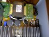
With the top case removed, a view of the main circuit. Transformer and large capacitors to the left, controller circuits/ inputs to the right. Small satellite board on the right is connected to the volume control. There's another board this connects to, which is the main display and all the front panel controls (between the long silver panel and the black plastic front cover).

IMG_20180115_230341.jpg

Closer view of the right hand circuit:

IMG_20180115_230350.jpg

Another view from the rear. The smaller circuit board suspended above the main board and connected via a ribbon cable is connected to the front panel and the volume knob:

IMG_20180115_230358.jpg

Closer view of the small board connected to the volume knob:

IMG_20180115_230406.jpg

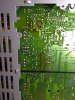
On the underside of the unit is a removable screw on access panel. Taking this off shows the underside of the circuit (controller board/ right side). This seems to show a couple of areas that might be where the problem(s) lie, appearing to show some areas of overheating:

IMG_20180115_230710.jpg

Larger suspicious area appears to be the IC-701:

IMG_20180115_231014.jpg

This is the IC701 as viewed from the top:

IMG_20180115_230833.jpg

IC701 is an NEC uPC2581V 9607B. Plenty available for sale online if this is what I need to replace.

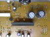
Here's the other area that shows signs of overheating:

IMG_20180115_231031.jpg

Q803, Q703 and some diodes/ other areas look suspect also.

Here's the view of Q803 and these areas from the top:

IMG_20180115_230908.jpg

Some odd looking black lines to right of Q801 and to the right of R807. No idea if they are simply marks on the board or if they are from components that have gone "pop".


Would be very grateful for any pointers as to where I should start looking, testing, and what components I should replace. Most of the components are pretty much standard and my soldering skills should be sufficient to replace most components on the board. Also, if any other pictures are required for further details, just ask and I will happily take some.

Looking forward to hearing some wisdom from the Electronics Point Gurus!
 

Attachments

  • IMG_20180115_230431.jpg
    IMG_20180115_230431.jpg
    334 KB · Views: 106
  • IMG_20180115_230726.jpg
    IMG_20180115_230726.jpg
    321.9 KB · Views: 106
  • IMG_20180115_230845.jpg
    IMG_20180115_230845.jpg
    286.4 KB · Views: 103
Last edited:

73's de Edd

Aug 21, 2015
3,622
Joined
Aug 21, 2015
Messages
3,622
Sir Chas . . . . .

Look VEWY-VEWY closely, with a visual acuity factor upped by a power of 10 to . . . .

IC701 pins 4-5-8-10-11-12-13 and all of Q803, as they certainly appear to have developed
" floating fractured solder ring joints" . . . . . .on some of their pins.
Liberally rosin flux and re flow solder ALL of the terminal joints with individual fresh addition of 60/40 solder.
Then, be expecting them to have a final look, and as good of a result as the "poster child" medium signal Q801 transistor nearby.

IC701 is being your driver for the POWER OUTPUT transistors mounted to the BIG heat sink nearby, check their solder joints also.

73's de Edd
 
Last edited by a moderator:

shrtrnd

Jan 15, 2010
3,876
Joined
Jan 15, 2010
Messages
3,876
My input is that I'd want to know the 'integrated house speaker' system layout.
I would first suspect the amplifier life-span was limited by the load (the 'integrated house speaker' system).
If I was doing this, I would be working under the assumption that I'd fix the amp, the owner would reinstall it, and
it'd be anybody's guess as to how long it would work with the original load re-attached.
It's always annoyed me when I make a repair, the owner repeats the mistake that fried the unit in the first place, and then complains to me that my repair wasn't up to snuff.
Just my opinion here. Your repair might work for however long the amp operated before this failure, but the damage I see is not what I'd expect to see if the amp was operated under the load for which it was intended. Additionally, there may be a problem in the house speaker system that should be identified, if this just wasn't over-taxing of the amplifier output.
 

kellys_eye

Jun 25, 2010
6,514
Joined
Jun 25, 2010
Messages
6,514
Have you done a basic check of the fuses and some static DC voltage checks? Some supplies are there given the LED status but this could be from a separately developed DC supply - the main DC supplies to the amplifier stage could be fused independently.
 

Chas

Oct 26, 2017
50
Joined
Oct 26, 2017
Messages
50
Thank you for the input everyone, it's always helpful to have much more experienced people help me rather than having me just diving in gung ho and hoping for the best.

kellys_eye, no, I haven't done any testing other than taking the covers off and giving it a visual inspection. I wanted to get some experienced opinions before going any further. Also, with the areas that appear to have overheated I suspected those may where most of the fault lies, thus those might indicate where I should be testing. As mentioned in my previous repair posts, my electronics knowledge is basic (though I am eager to learn), and with some guidance from the electronic meisters I will then get some ideas of the next steps to take.

shrtrnd - the integrated house speakers were simply built in speakers in the house. Or rather, in the ceiling in the family room and kitchen (A + B sets of speakers). They resemble car type speakers, round and flush mounted. Not very powerful by the looks of things, certainly not enough to overload the amp. You are most correct by stating that a fault may be in the speaker/ wiring that is causing a load issue and hence the fault in the amp. I would be sure to check these if/ when the amp is repaired. It is also worth pointing out that the amp/ speakers aren't used much as the lady who lives there is a snow bird, though she actually spends over half the year up north. When she is away the house is unused. Oh, and I did a search online and found numerous other occurrences of similar model Sony amps developing the same faults, so it might actually be a weak spot in the design.

73's de Edd, awesome observations and advice, and yes, that will be my first plan of attack. I will remove as much of the old solder as possible and then resolder all those joints you mentioned. I'll also redo all the large transistors while I'm at it. Then I will retest the system to see if there's any improvement, and also start hunting about for voltages. Maybe it will be similar to the food processor I repaired a few months that Dorke expertly pin pointed the fault to a blown zener diode. Only one way to find out, and I'm off to fire up the soldering station right now.

I will report back!
 

Chas

Oct 26, 2017
50
Joined
Oct 26, 2017
Messages
50
UPDATE:

I have re-soldered IC701, Q801 and Q803, and also the four large transistors bolted onto the central heat sink. I then powered up the unit, and there's no change. Still had the bass boost LED coming on and working with its button, and can still hear the transformer "click" on initial power on.

As IC701 is the driver for the power output transistors, perhaps that is not the cause of the display and unit functions not working? More so, as I examined the area of Q803 and Q801, which is also adjacent to the area where the front panel display connects.

Here are some pictures of these areas from above and below.

IMG_20180117_234740.jpg

IMG_20180117_232643.jpg

Red circle shows the front display panel ribbon connector, and the pink circle shows the area of transistors/ diodes and signs of overheating.

At the top left you can see "+5v" on one of the circuit board tracks, and when I tested this with my DMM it did indeed show 5 VDC. I tested for voltages around the Q803/ 801 and diodes area and got some voltages mostly of 0.5 VDC with a couple of areas of 1 VDC.

I also had a peak at the satellite volume control board and was reading some very low voltages (approx. 0.2VDC) from the resistors and jumper wires.

IMG_20180117_234802.jpg

There is clearly power getting to the boards, which is a good sign. What would be the next step? I have tried looking for a schematic online, but no luck, so I'm kind of lost at sea at this point. Without any help, I would use a process of elimination and start replacing the Q803/ Q801 transistors seeing as they appear to be closely connected with the front display panel connector, and also the nearby diodes. My logic would be to swap out the overheated area components as they are suspected to have run hot and burnt out. That could also include the IC701, though as that doesn't seem to be directly connected with the display I would put that further down the list. Or if anyone could suggest what I should be testing for next that would be a great help and much appreciated!

Also, I can't find any fuses on any of the boards (transistor and power amp areas also). At least not the glass or ceramic types I'm used to seeing. Unless it's using fusible links that I'm not seeing?
 

kellys_eye

Jun 25, 2010
6,514
Joined
Jun 25, 2010
Messages
6,514
You need to be in the 'other side' of the unit before anything else. The big mains transformer has a fuse board on its input but these are likely to be ok as you wouldn't measure anything if they were blown.

Measure the voltages on the multiway connectors on the power supply board and let us know your readings.
 

Chas

Oct 26, 2017
50
Joined
Oct 26, 2017
Messages
50
Thanks Kellys+eye. I will most certainly test for voltages as you said. However, before I do that, a little bit of rooting around tonight found something I had missed previously.

There's a small board connected to the transformer. On top it says 5A/ 125V (in hindsight it should have been obvious!) Looking through the gap there appears to be a glass tube...

IMG_20180118_231512.jpg

Looking underneath, and sure enough, there's the elusive fuse hiding there that I was unable to find previously!

IMG_20180118_231603.jpg

I know it should have been obvious from the 5A/ 125V written on the board, but remember, I'm still green round the ears when it comes to electronics.

I removed the fuse and...


IMG_20180118_192853.jpg

It clearly appeared to have blown. I double checked it with my DMM just to be certain and sure enough, it was dead.

Some progress then, as this might be why nothing else is powering up. Of course, why it blew in the first place needs to be investigated, however, unless I replace it I won't find out.

The markings on the fuse indicate:

5A 125V BUSS GMC SA U1

On the board it shows:

F901
5A/ 125V
(U/CA)

A little bit of research shows them to be "medium blow" fuses (Bussman GMC series). Which is a pain as "medium blow" are harder to find compared with fast or slow blow fuses.

This seems to be the cheapest option, though as they are coming via the slow boat from China I would have to wait a while before moving getting to work on the unit again.

https://www.ebay.com/itm/5Pcs-Bussm...879514&hash=item27f1cc5108:g:pWgAAOSwTO9aRLJH

Before I hit buy it now on the fuses, can anyone confirm that they are indeed the correct type? Or if anyone knows an alternative source I can use at affordable prices, then that would be great to know,
 

73's de Edd

Aug 21, 2015
3,622
Joined
Aug 21, 2015
Messages
3,622
Sir Chas . . . . .

Initial Question?
OK, so you have the complete manual downloaded from Libmanuals site and all of the 50 pages of just its schematics.
Our point of interest will be ~ its Page 201.

Did you only get a HTML version with its limitations of having to use that portable magnifier lens . . . which is what they have being available on the manuals site . . . . . or did you get a full blown PDF version . . .that gives you unlimited blow up capability . . . plus its almost infinite definition?
The HTML version is somewhat limited in definition of viewing some parts if using the magnifier.

Continuing . . . . .


There is one power supply in the unit which is being a linear design standby power supply for a portion of the unit.
That F901 fuse is related to the somewhat HEFTY switch mode power supply portion of that unit, so you would NOT want to just put in another fuse and TRY it out. Since that fuse shown was HARD blown.

I would have to wait a while before moving getting to work on the unit again.
Au contraire . . .
Instead, you want to rig wiring and socket to be able to connect a 60 watt incandescent lamp in place of the fuse.
Then you power up the unit and see if you get an instantly bright light from the lamp or if it only comes up to a dull orange glow and then a dimming.
If getting a bright glow, one would expect a shorted D901 Full Wave bridge rectifier unit or the pin 3 of the IC 902 power switching unit is shorted internally to its pin 2 hot ground. .

73's de Edd
 

Chas

Oct 26, 2017
50
Joined
Oct 26, 2017
Messages
50
73's de Edd, I didn't have any manuals at all until you mentioned it!

I did a search for a service manual for the STR-DE305 and this is what I found:

https://www.manualslib.com/s/str-de305.html

The service manual is 38 pages, I can't see a page 205 anywhere though.

I also managed to download all three manuals including the service manual as PDF's so yes, I can magnify them and make them clear and easy to read. I wish I could understand the service manual schematics better though.

Next step, I will wire up a bulb holder to the fuse points and try it with a 60w bulb. Pretty sure I have some spare bulb holders that were swapped out for LED lights, so they will easily take a 60w filament bulb. As soon as I do that and run the test, I shall report back.
 
Last edited:

Chas

Oct 26, 2017
50
Joined
Oct 26, 2017
Messages
50


There is one power supply in the unit which is being a linear design standby power supply for a portion of the unit.
That F901 fuse is related to the somewhat HEFTY switch mode power supply portion of that unit, so you would NOT want to just put in another fuse and TRY it out. Since that fuse shown was HARD blown.

I would have to wait a while before moving getting to work on the unit again.
Au contraire . . .
Instead, you want to rig wiring and socket to be able to connect a 60 watt incandescent lamp in place of the fuse.
Then you power up the unit and see if you get an instantly bright light from the lamp or if it only comes up to a dull orange glow and then a dimming.
If getting a bright glow, one would expect a shorted D901 Full Wave bridge rectifier unit or the pin 3 of the IC 902 power switching unit is shorted internally to its pin 2 hot ground. .

73's de Edd


I have wired up a 60 watt filament lamp to the connections of the F901 fuse as you said.

Switched the unit on, and it instantly goes to maximum brightness and stays there. No variation in brightness. The lamp will also turn on and off with the Sony front power switch.

Sorry if I'm dim and missing something, but I cannot find any mention of a D901 or IC902 in the service manual PDF (the manual I linked to above)?

What's the next step to take from here?
 

73's de Edd

Aug 21, 2015
3,622
Joined
Aug 21, 2015
Messages
3,622
Sir Chas . . . .

Suspects . . . . . . . . are being marked in bottom left corner area with fine RED lined rectangles and BLACK stars . . .will fill you later if the pins of the IC902 are not silk screened on the board.

SPECIAL PHANTOM BOARD LAYOUT INFO . . . . .

DENON_S_301_P.S._BOARD.png


73's de Edd
 

Chas

Oct 26, 2017
50
Joined
Oct 26, 2017
Messages
50
73's de Edd, I really appreciate your input. However, are you sure we are on the same page (literally!)?

The circuit diagram above is for a Denon STR-F6238S/ 6267S.

My unit is a Sony STR-DE305.

The schematics/ service manual for this Sony model I found here:

https://www.manualslib.com/s/str-de305.html

Here are two shots of the schematics showing the main circuit board, and also of the smaller boards including the "primary", which is where the F901 fuse is:

Main Circuit.png
Additional Circuits.png

I can confirm that the above circuit layouts match the Sony STR-DE305 that I have exactly.

Could you please look over those and then see which parts might be faulty, and which I need to test/ replace next? There's also a list of all the components used in the PDF link above.

Many thanks in advance!
 

73's de Edd

Aug 21, 2015
3,622
Joined
Aug 21, 2015
Messages
3,622
Sir Chas . . . .

Indeed . . . I do now see that I had posted info relevant to another persons equipment . . . . here is your units specific info, below :

The most suspect failure condition would seem to be a Collector to Emitter short being present on one or more of the Q703 and 704 and Q753 and Q754 power output transistors that are mounted to the massive heat sink.
They are fed directly by the MAIN +58V and -58V power supplies.
That condition would be pulling enough excess current to pop the F901 fuse
Also the FULL WAVE RECTIFIER BLOCK, D802, ( in pink highlighting) which contains 4 internally potted in diodes needs to be tested, as its failure could also pop the fuse.
Get those parts tested out initially. If power out transistors are found bad, that potentially could relate to the floating ring joints found on the driver IC which could have temporarily / intermittently upset drive biasing to a set of output transistors and they crashed and burned in having been mis-biased into too hard of a state of conduction by the driver IC.

POWER SUPPLY SNIPPET OF SONY STR-DE305 . . . . .

upload_2018-1-21_1-41-4.png


73'S de Edd
 
Last edited by a moderator:

Chas

Oct 26, 2017
50
Joined
Oct 26, 2017
Messages
50
73's de Edd, thank you for the details and schematic of where to test next.

I've tested for voltages at all the components mentioned, with the unit powered on though without either the F901 fuse in place or the test load 60W filament lamp bridging the fuse links. I wasn't sure if either of those needed to be in place to run the test, so I erred on the side of caution and ran it without them.

For Q801, Q803, D801, D804 and D805, I took a picture of the board and then used Paint to write in the voltage readings at the test points on the boards. These are the readings I got:

IMG_20180121_221731 Voltages.jpg

I am wondering if D801 may be blown, as on the circuit track that it reads 0.0V, none of the other points also on that track read any voltages?

For Q703/ 794/ 753/ 754, I tested the voltages on all three legs of each transistor. All four transistors gave the same readings on each of their three legs. Leg 1 = 0.07V, Leg 2 = 0.5V, Leg 3 = 0.5V.

For D802, I could only test the four legs from above as the service panel at the bottom of the unit did not give access from underneath. From above, the top pin is marked as "+" on the board and the bottom pin is marked as "-". Going from top to bottom:

Pin 1 (+) = 0.5V
Pin 2 = 0V
Pin 3 = 0V
Pin 4 (-) = 0.5

If you need me to re-run the tests again with the test lamp in place of the fuse, let me know and I will do so. I have yet to purchase a fuse to replace the F901 that blew as you said to hold off replacing the fuse for now.

Thanks again for your help, and hopefully the above readings may shed some light on what steps to take next.
 

Chas

Oct 26, 2017
50
Joined
Oct 26, 2017
Messages
50
Sir Chas . . . .

Indeed . . . I do now see that I had posted info relevant to another persons equipment . . . . here is your units specific info, below :

The most suspect failure condition would seem to be a Collector to Emitter short being present on one or more of the Q703 and 704 and Q753 and Q754 power output transistors that are mounted to the massive heat sink.
They are fed directly by the MAIN +58V and -58V power supplies.
That condition would be pulling enough excess current to pop the F901 fuse
Also the FULL WAVE RECTIFIER BLOCK, D802, ( in pink highlighting) which contains 4 internally potted in diodes needs to be tested, as its failure could also pop the fuse.
Get those parts tested out initially. If power out transistors are found bad, that potentially could relate to the floating ring joints found on the driver IC which could have temporarily / intermittently upset drive biasing to a set of output transistors and they crashed and burned in having been mis-biased into too hard of a state of conduction by the driver IC.


73'S de Edd

73'S de Edd, any suggestion as to what steps I should take next? Did I run the voltage reading tests correctly, or do I need to re-do them with the test lamp in place of the fuse?

Other than starting to replace all the suspect components, I'm not sure what direction to take next!
 

Chas

Oct 26, 2017
50
Joined
Oct 26, 2017
Messages
50
Well, with no further input to my findings above, and not knowing quite which direction to take next, I started hunting round the 'net and Youtube to see if I could find information on testing the suspected output transistors and the full wave rectifier. Luckily I found a video of someone repairing a similar Sony audio receiver unit that shared the same output transistors. The unit he was working on also suffered failed output transistors, and better still, @14.40 he showed how to test the test the new items he had to confirm they were OK.


To make testing easier and more accurate, I pulled all four output transistors from the board, along with the bridge rectifier:

IMG_20180201_020813.jpg


The unit I am working on also uses MP1620 and MN2488 transistors in two pairs, so I tested them with my DMM in diode mode. Here are the results (1 and 2 are the first pair on the board, 3 and 4 are the second):

1. MP1620

Base to Collector = 450
Base to Emitter = 450
Collector to Emitter = 0
Collector to Emitter (reverse bias) = 0

2. MN2488

Base to Collector = 460
Base to Emitter = 460
Collector to Emitter = 0
Collector to Emitter (reverse bias) = 0

3. MP1620

Base to Collector = 450
Base to Emitter = 526
Collector to Emitter = 1
Collector to Emitter (reverse bias) = 360

4. MN2488

Base to Collector = 477
Base to Emitter = 560
Collector to Emitter = 1
Collector to Emitter (reverse bias) = 360

Going by the test shown in the video linked above, can it be deduced that the 1 & 2 pair of transistors are faulty? The 3 and 4 pair appear to behave in much the same way that the "good" transistors behaved in the video above, whereas 1 and 2 did not.

I've found the same transistors for sale on Ebay for a bargain price for two pairs, so would think it might be prudent to just go ahead and replace them all while they are out of the board.

https://www.ebay.com/itm/2pairs-of-...hash=item3f198a809a:m:mkmjfsrc5cr8QelE1X4ac0Q

I also note in the video that the problem was also linked to a resistor in front of the faulty pair of transistors. The amp I am working on also has two similar looking resistors, one in front of each pair of transistors. I can't test these for voltages though, as asides from not having the fuse in place, the resistors on my board don't have the pins sticking out of their tops. Should I just go ahead and replace these resistors as a matter of course?

Here's a picture of one of the resistors:

IMG_20180201_020836.jpg

This now leads me to the full wave bridge rectifier unit. I found another very helpful video showing a guy testing a similar unit in a TV power board. @1.50 you can see the guy showing how he checked the full wave rectifier unit using a DMM in diode mode:


I pulled the full wave diode unit from the STR board and did the same. Using the pin-out as 1 = Negative, 2 = A/C, 3 = AC and 4 = Positive, I got the following results:

Pins 1 and 2 = 377
Pins 1 and 3 = 374
Pins 1 and 4 = 900

Then reversing the probes and repeating the test:

Pins 1 and 2 = 1
Pins 1 and 3 = 1
Pins 1 and 4 = 1

Here are some pictures of me carrying out the test with my DMM:

IMG_20180129_230958.jpg IMG_20180129_231010.jpg IMG_20180129_231020.jpg IMG_20180129_231045.jpg IMG_20180129_231057.jpg IMG_20180129_231110.jpg

Going by the video, the chap said any readings less than 400 or more than 700 was indicative of a problem with the bridge rectifier. Two of the results were close to 400 so might be OK, though pins 1 and 4 showed 920 that is much higher than it should be. Once again, I am assuming that I should go ahead and replace the full wave rectifier unit as a matter of course, especially in light of the above results?

The bridge rectifier on the board is a identified as RBV-602. I did some searching, but couldn't find this exact model for sale anywhere. I did find a data sheet for it:

http://pdf.datasheetcatalog.com/datasheet/eic/RBV604.pdf

The crucial details appear to be that it is a 200v 6a full wave bridge rectifier. I found an equivalent, GBU603, on the Mouser website:

https://www.mouser.com/productdetail/taiwan-semiconductor/gbu603?qs=G5AQjGfRJcL/c/7k5b2iLw==

However, it says that they don't carry it in stock (I've sent a pricing and delivery request, awaiting a response). I did find a couple on Ebay (GBU603):

https://www.ebay.com/itm/GBU603-Tai...377376&hash=item212391fccd:g:fPsAAOSwLVZVyaFk


In conclusion, if I understand correctly, it appears that two of the transistors are faulty, and the bridge rectifier is also suspect. I assume that the next step would be to replace those, and possibly the two resistors in front of the two pairs of transistors? And obviously the fuse as well.

Any input/ advice/ suggestions/ words of wisdom would be gratefully received! :)
 

73's de Edd

Aug 21, 2015
3,622
Joined
Aug 21, 2015
Messages
3,622
Sir Chas . . . . .

If you will, place metering in ohms function and in the lowest ohms range . . . unless it is doing it for you by being autoranging.. . . then do this test.
Place meter leads together and expect a low reading for the short you are creating, open the leads and expect the "1" open circuit meter indication.
Checking the 1 and 2 transistors and being in the ohms function and metering between C and E should show a short, with either lead polarity applied.
Doing the same test on 3 and 4 transistors should get the "1" reading . . . for a good pair.
Probably no damage was done . . . . but test the WHITE emitter resistor sets by placing either meter lead to the common center lead and then read resistance to one and then the other end leads. They would both read the 0.22 ohm resistance plus the resistance of the test leads.
Only being bad, if getting the "1" reading, and it would be the unit tied into the 1-2 transistor pair . . . .really not expected them to be bad.
Your bridge rectifier reading looks good also.

Was the link in the fuse vaporized or had it blackened the inside glass of the fuse casing ?
That is what a shorted bridge rectifier usually produces.

Let's put the bridge rectifier back in . . .correct polarity . . . and leave the two bad POWER transistors out.
Then you can use the same protective series lamp, for permitting a non destructive power up testing.
Do just a 3 second power up to see if the lamp is BRIGHT . . .BAD . . .or just a medium glow and dimming.
If the latter, you can check the RED and BLACK SQUARE voltages to see if they are about the same value, since
we are operating on reduced voltage input now.
Also the RED and BLACK ARROW voltages, which should probably clear any suspicions of the Zener diodes that you tested earlier.
Get caught up on this and I will prepare a relevant schematic snippet of the audio output circuitry of the bad channel to see if some transistors that feed into the two bad power transistors might have also been crunched.

73's de Edd
.....
 

Chas

Oct 26, 2017
50
Joined
Oct 26, 2017
Messages
50
Thanks so much 73's de Edd. Your words of wisdom and help are very much appreciated.

Sir Chas . . . . .

If you will, place metering in ohms function and in the lowest ohms range . . . unless it is doing it for you by being autoranging.. . . then do this test.
Place meter leads together and expect a low reading for the short you are creating, open the leads and expect the "1" open circuit meter indication.
Checking the 1 and 2 transistors and being in the ohms function and metering between C and E should show a short, with either lead polarity applied.
Doing the same test on 3 and 4 transistors should get the "1" reading . . . for a good pair.

I set my DMM to 200 ohms (the lowest it would go), tested the two pairs of transistors, and you were right. The suspect pair (1 & 2) did indeed both show a short (low reading) between C & E, and also when reversed biased. The "good pair" showed "1" between C & E, and gave a much higher reading when reversed biased. From my understanding, this shows that the diodes in the good pair (3 & 4) are doing their jobs and only allowing the current to flow in one direction. The bad pair (1 & 2) show a short, meaning the diodes aren't doing their jobs.

Probably no damage was done . . . . but test the WHITE emitter resistor sets by placing either meter lead to the common center lead and then read resistance to one and then the other end leads. They would both read the 0.22 ohm resistance plus the resistance of the test leads.
Only being bad, if getting the "1" reading, and it would be the unit tied into the 1-2 transistor pair . . . .really not expected them to be bad.

I tested the two white emitter resistors (in circuit) as you advised above. Set the DMM to the lowest setting again (200 ohm) and tested both end pins with one lead connected to the center pin. I got readings of 0.6 ohm for all four readings (2 x readings for each of the 2 x resistors).

Your bridge rectifier reading looks good also.

That's good to know!

Was the link in the fuse vaporized or had it blackened the inside glass of the fuse casing ?
That is what a shorted bridge rectifier usually produces.

See pics below, they will explain the fuse condition better than I can:

IMG_20180202_205518.jpg IMG_20180202_205542.jpg


Let's put the bridge rectifier back in . . .correct polarity . . . and leave the two bad POWER transistors out.
Then you can use the same protective series lamp, for permitting a non destructive power up testing.
Do just a 3 second power up to see if the lamp is BRIGHT . . .BAD . . .or just a medium glow and dimming.
If the latter, you can check the RED and BLACK SQUARE voltages to see if they are about the same value, since we are operating on reduced voltage input now.
Also the RED and BLACK ARROW voltages, which should probably clear any suspicions of the Zener diodes that you tested earlier.
Get caught up on this and I will prepare a relevant schematic snippet of the audio output circuitry of the bad channel to see if some transistors that feed into the two bad power transistors might have also been crunched.

73's de Edd
.....

Bridge rectifier and the pair of good transistors are back in place. Polarity correct for the rectifier (the board helpfully has "+" and "-" printed on it, plus it matches the orientation in the photo I took before I removed it). The output transistors are in the correct place for each of the two types, again, the circuit board has the component numbers printed on it, plus I compared it with the photo I took of them prior to removal. The bad transistors have been left out.

I just need to get the board back in the case and then hook all the connectors back up. I'll do that later tonight, and then fire it up with the test lamp in place. I shall report back with my findings as soon as I get them. Fingers crossed!
 
Top