Maker Pro
Maker Pro

Stuck detecting 'engine running' from alternator 'W' signal

JohnW

Aug 2, 2017
22
Joined
Aug 2, 2017
Messages
22
Hello,

I am really stuck with something that seems simple, but a simple solution, or any is eluding me at present.

I am building an engine monitoring system for a boat diesel engine. I am using an Arduino, and have most of the programming and signal conditioning cracked, I hope.

In order to prevent the system alarming when the engine is not running, I need to detect when it is running, and will also keep track of engine run time by this means. To do it, I need to turn on a transistor, to pull a digital input down to near 0v.

I had hoped that I could clamp the signal from the alternator, and use the positive voltage to drive the transistor base, via an RC combination to hold it on while the signal is present.

I have not measured the signal from the alternator, (the boat is in France) but believe this to be derived from the unrectified stator winding, believed to be sinusoidal, and about 8 volts rms. It will be shared with a new tachometer via a 0.1 uf capacitor. Again an assumption is that when running the engine operates at between 800 rpm and 2500 rpm, via pully that probably doubles this and there are 6 poles in the alternator. So( 800 x 2 x 6) / 60 = 160Hz at idle.

I have 5 volts derived from the Arduino to play with, and need to pull this down to system ground via a 10K internal pullup.

I figure that with a sinusoidal input I cannot easily trigger a monostable circuit. My clamping mechanism doesn't generate sufficient current to drive a transistor on. I am currently limited to testing with a square wave, which of course produces pulses on the rising and falling edge, and the dc voltage generated only amounts to about 1.5 volts.

This must be done in every tachometer like mine, which does record run time when the engine is running, but I have been unable to find out how they do it.

Can anyone help or shed some light on this?

Thanks in anticipation...

John
 

Alec_t

Jul 7, 2015
3,590
Joined
Jul 7, 2015
Messages
3,590
Would something like this meet your needs? It will accept alternator voltages from around 3V rms to at least 50V rms and will have little effect on the tacho drive signal.
I don't understand what your clamping arrangement is.
Alternator_to_Arduino.PNG
 

JohnW

Aug 2, 2017
22
Joined
Aug 2, 2017
Messages
22
Hello Alec

This is basically what I have been trying to build! Or something very close to it.

The 'clamp' I referred to is D2 which passes negative the negative going part of the cycle to ground, resulting in a mainly positive voltage at its junction with R1/D1.

I have tried playing with different values of R2, and have had a larger capacitor at C2. I have not had R1 in place, and am not sure what this would do for you, other than increase the impedance and reduce the impact on the tacho signal. The tacho comes with an external capacitor, and I was planning to keep the two separate - in parallel in effect.

I've not been getting enough voltage to drive the transistor on. I am thinking that a Shotky diode in both positions would help. In D2 to get more positive volts, and in D1 to drop less.

I don't have enough input volts to drive it with a sine wave, and the square wave if of about the right amplitude, but producess some more spikes than I would like.

The trace is pretty convincing! Have you in fact built and tried this?

Thanks for your interest, and I will have another go keeping to your parameters. I have a 50 year old electronic engineering degree, but never afterwards designed a single circuit in anger. I did try to use a FET for analogue sampling during a training assignment, but that wasn't too successful either.
 

kellys_eye

Jun 25, 2010
6,514
Joined
Jun 25, 2010
Messages
6,514
How about detecting the field current in the alternator armature (via the ignition lamp) i.e. when the ignition light is out a relay switches power to the hours-run meter. Obviously the power for the detection/meter should be via the ignition switch.
 

WHONOES

May 20, 2017
1,217
Joined
May 20, 2017
Messages
1,217
Might be a bit more work, but what about a small magnet on a rotating part in conjunction with a hall effect detector?
 

Bluejets

Oct 5, 2014
6,927
Joined
Oct 5, 2014
Messages
6,927
If you are already using Arduino, why not simply feed the battery charge voltage level into a spare analog input ( or rather a resistor divider derived voltage)
It's a fairly easy couple of lines of code ( if > x volts then do this, else, do that)

Arduino input will only handle up to 5v max.

Nothing new about the idea AND it works.
You could make one end of the divider an adjustable pot for fine level detect if that floats your boat. :) :)
 
Last edited:

Externet

Aug 24, 2009
891
Joined
Aug 24, 2009
Messages
891
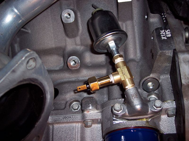
Or, erase the blackboard about using the alternator and implement an oil pressure switch that will ground when there is no oil pressure. That warns the engine is not running.
 

Bluejets

Oct 5, 2014
6,927
Joined
Oct 5, 2014
Messages
6,927
Or, erase the blackboard about using the alternator and implement an oil pressure switch that will ground when there is no oil pressure. That warns the engine is not running.

mmm...maybe still running BUT not for much longer.:eek::eek:
 

JohnW

Aug 2, 2017
22
Joined
Aug 2, 2017
Messages
22
detecting the field current in the alternator armature (via the ignition lamp)

If I recall correctly the regulator normally controls the field current in the armature. This field current is supplied by a rectified output from the stator, and is in some setups primed initially by the current flowing through the warning lamp from the battery - although residual magnetism would probably do the job.

In our case the alternator does not normally come with an external field connection, although we have an 'intelligent' charge controller that contrives to achieve 3-stage charging via a wire soldered onto the field supply. So it is not really available to us: the controller may be saying "charge me". We have no ignition warning circuit as such.

The 'W' terminal is unrectified stator output (but may be a tap on the coil) and is used by the tachometer. The tachometer has an engine hours meter that only runs when the engine is running, not just when power is applied. So a solution exists!
 

JohnW

Aug 2, 2017
22
Joined
Aug 2, 2017
Messages
22
Might be a bit more work, but what about a small magnet on a rotating part in conjunction with a hall effect detector?

Believe me, new engineering on a boat is never that simple. It invariably means emptying cupboards, removing covers, floors, and introducing cables through channels that are already stuffed full.

I am replacing an existing instrument that is no longer made. The cables are all in place.
 

JohnW

Aug 2, 2017
22
Joined
Aug 2, 2017
Messages
22
mply feed the battery charge voltage level into a spare analog input (5 :)

I already have the battery voltage being measured. If the batteries were fully charged you could pick up the rise in voltage above, say 12.8 volts, but if the batteries were down for some reason then this would not be achieved for some time.

And to the other contributor, the oil pressure transducer is an analogue one, and is also being measured. One objective is not to alarm for low oil pressure unless the engine has been running for aa few seconds.
 

Externet

Aug 24, 2009
891
Joined
Aug 24, 2009
Messages
891
If you do not like implementing an additional oil pressure sensor with a simple T fitting,


iu


attaching a microphone to the block is an alternative. They are also cheap, abundant, called automotive knock sensors. A circuit to amplify and handle time-to-response will give the desired delay to tell if the engine is running or not.
images

----> https://okystar.com/product-item/knock-sensor-knock-module-oky3438/
 
Last edited:

JohnW

Aug 2, 2017
22
Joined
Aug 2, 2017
Messages
22
Would something like this meet your needs? I]

Alec,

Indeed it does! Thanks very much for your input.

I built your circuit just as it is. shown above. My testing is limited to a multivibrator presently running at around 400 Hz and feeding the capacitor with a 12 volt peak to peak square wave, that is fairly faithfully reproduced by the capacitor, clamped to near enough 0v. Obviously a sinusoidal input at a greater voltage will behave differently, but we will worry about that when I am on the boat.

Initially I was seeing a triangular waveform at the junction of D1 and R2, and it was insufficient to saturate the transistor, so that a similar waveform appeared at the collector of Q1. I increased C2, I think I now have a 1uF (markings not great) which smoothed out the waveform. A larger capacitor (10 uF)did not in fact help. I then reduced R2 by degrees to 33K. In the end I had around 3 volts at C2/R2 and the transistor is fully on.

I'll look at the alternator output and possibly put a diode at R1/D2 to dump any voltage above 5 volts.,,maybe this is better at D1/R2.

I had tried a forward diode in the place of R2 and a resistor in place of D1, but that did not work!

Thank you again for your help.
 

Alec_t

Jul 7, 2015
3,590
Joined
Jul 7, 2015
Messages
3,590
No, I didn't build the circuit. Glad you have it working with a few tweaks.
 
Top