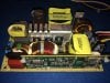
Hi all. I have a question about a power supply. Input is 120vac. There are two outputs. One is a four wire 12vdc (two pos, two neg, hooked to a single pos and single neg output on the board) and the other is 52vdc (one pos and one neg). This thing runs a surveillance system (cameras and a DV recorder).
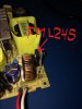
My question is this, should both outputs (12, 52) always have the rated voltage when the AC voltage is supplied to the unit, or is it possible one of them (the 52) would not show any (other than a small mv) until something triggers it and that is why it is called a SMPS? I wonder this because I do not see any other wires coming from or going into the power supply that would logically return a signal from the rest of the DVR to trigger anything. There is another PCB (you can see it in pic 3) on the side of the PS with another bunch of components. Part of it runs a 12 volt cooling fan, which is working properly. As I am reading this for errors prior to posting, I am wondering now if that secondary PCB may have wi-fi components, which would turn on the power supply (52V) to activate the recording?
The 12 volt side is producing 11-11.5 vdc. So I'm good there. The 52v side is not producing anything from the wire outputs. However, when I take a reading from the heat sink (which is attached to some mosfets/transistors and a diode) in the middle of the board (it has the number "2" on it), I am getting +51.5vdc to the chassis ground. I also get a steady 64.7vac (either probe) doing the same thing with the DVM set on AC. The DC voltage is not steady and goes up and down a fraction of one volt. Oddly though, the negative lead on the DVM has to be on the heatsink and the positive on the ground to get a positive DC reading. To my non-electronic educated self, that should make no sense. Based on the power supply box design, however, I do think some voltage should be there (on the heat sink), because the inside of the enclosure has insulation material positioned above it. By the way, don't ask me how I found out about the voltage coming off the heat sink.")
Note that the original power mosfet, all other mosfets, and all of the transistors have been replaced, as have all of the caps. The diode was removed and checked. It is operating properly. All components were replaced with the same as what was removed, and before you ask, they were put back in the same way as they came out. I don't have the rest of the DVR to plug it in to test it, so I'm hoping that is the only reason I am not getting the higher voltage reading at the wire outputs.
Does anyone know if it is probably operating correctly, or what should I check next? I see places on the bottom of the PCB that may be test points, but unless a/the "switch" has to be activated for the 52 volt side, I don't know how to do that. I do not have a schematic. It is a Delta DPS-200PS-185B power supply.
Thanks in advance for your reply.
My question is this, should both outputs (12, 52) always have the rated voltage when the AC voltage is supplied to the unit, or is it possible one of them (the 52) would not show any (other than a small mv) until something triggers it and that is why it is called a SMPS? I wonder this because I do not see any other wires coming from or going into the power supply that would logically return a signal from the rest of the DVR to trigger anything. There is another PCB (you can see it in pic 3) on the side of the PS with another bunch of components. Part of it runs a 12 volt cooling fan, which is working properly. As I am reading this for errors prior to posting, I am wondering now if that secondary PCB may have wi-fi components, which would turn on the power supply (52V) to activate the recording?
The 12 volt side is producing 11-11.5 vdc. So I'm good there. The 52v side is not producing anything from the wire outputs. However, when I take a reading from the heat sink (which is attached to some mosfets/transistors and a diode) in the middle of the board (it has the number "2" on it), I am getting +51.5vdc to the chassis ground. I also get a steady 64.7vac (either probe) doing the same thing with the DVM set on AC. The DC voltage is not steady and goes up and down a fraction of one volt. Oddly though, the negative lead on the DVM has to be on the heatsink and the positive on the ground to get a positive DC reading. To my non-electronic educated self, that should make no sense. Based on the power supply box design, however, I do think some voltage should be there (on the heat sink), because the inside of the enclosure has insulation material positioned above it. By the way, don't ask me how I found out about the voltage coming off the heat sink.
Note that the original power mosfet, all other mosfets, and all of the transistors have been replaced, as have all of the caps. The diode was removed and checked. It is operating properly. All components were replaced with the same as what was removed, and before you ask, they were put back in the same way as they came out. I don't have the rest of the DVR to plug it in to test it, so I'm hoping that is the only reason I am not getting the higher voltage reading at the wire outputs.
Does anyone know if it is probably operating correctly, or what should I check next? I see places on the bottom of the PCB that may be test points, but unless a/the "switch" has to be activated for the 52 volt side, I don't know how to do that. I do not have a schematic. It is a Delta DPS-200PS-185B power supply.
Thanks in advance for your reply.