Maker Pro
Maker Pro

Technics SA-5760 Receiver No Output

KilgoreCemetery

Apr 12, 2017
258
Joined
Apr 12, 2017
Messages
258
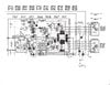
At first, the protection relay would click on and off sporadically and I was able to trace the problem down to the driver board having voltage spikes in the signal path of one channel. The board mounts vertically, so I had this bright idea of removing it and putting it in the freezer for a minute, then reinstalling it and warming up the transistors with the tip of my soldering iron one at a time. Silly me, the cold must have killed whatever was working intermittently and now I have positive rail voltage in all sorts of places on the board that it shouldn't be.

-I've tested all of the diodes on the board and they are all good.
-I've replaced all of the electrolytic capacitors on the board because I plan on recapping the entire unit anyhow.
-I've replaced all but one of the transistors on the positive, "push" side, of the channel
-I swapped the remaining positive, "push" side, transistor out with the one from the working channel

I'm still getting about +58V in all sorts of places it shouldn't be. Including on the base and emitter of both the main push and pull output transistors for one channel.

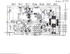
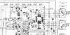
It won't let me upload the service manual I found on HiFiEngine, but I do have a diagram for just one channel that I've been writing voltages on. Everything in blue ink is from the working channel, voltages in pencil are from the non-working channel.

Can anyone give me some ideas for what else I can check? I'm 99% sure that the positive rail voltage is leaking into the pull-down side of the circuit, but I can't tell from where.
 

Attachments

  • Technics SA-5760 WIP.jpg
    Technics SA-5760 WIP.jpg
    309.7 KB · Views: 8

73's de Edd

Aug 21, 2015
3,622
Joined
Aug 21, 2015
Messages
3,622
Sir Kilgore Cemetery . . . .

( How you ever get anyone "planted" . . . with all of this here electronics tom-foolery going on ?)

It sort of looks like your trouble onset origin is possibly being at the base of the TR605 transistor
( leaky or shorted TR605 ? ) at the schema far left.
Or possibly a bad / leaky D601.

Then, thereby, there is being far to much + voltage on every direct DC coupled transistor stage, passing on down to the right, but your schema snippet did clip off the showing of your pairs of darlington arranged POWER output transistors.
PLUS is the .33 ohm R699 emitter resistor good ?

Not a good idea on freezer chilling a board like that and then powering up with upwards of + - 60 VDC, being on the board, as you KNOWS, that there is then going to be a potentially conductive film of water condensate starting to form all over the board, as it gradually comes up to room temperature.

73's de Edd
. . . . . . . . . . .


You just " GOTTA " see my newly developed set of tin cans-and-string telephones . . . . resplendently complete with its third can . . . for call waiting . . . or conference calls !
 
Last edited:

KilgoreCemetery

Apr 12, 2017
258
Joined
Apr 12, 2017
Messages
258
I almost planted one once, but I'm far more of an audio nut than I gardener, it seems.

It sort of looks like your trouble onset origin is possibly being at the base of the TR605 transistor
( leaky or shorted TR605 ? ) at the schema far left.
Or possibly a bad / leaky D601.
That's where I was looking too. I've already replaced TR605 with a new generic and just now swapped out D601, but I'm still getting about 58V on the base / emitters of the main output transistors for this side.

Near as I can tell, R669 is good. My multimeter doesn't read down that low very well, but it looks to be in good shape physically and doesn't show as open.

Frozen circuit boards seemed like a good idea at the time, but I think I'll try some freeze spray next time instead. Definitely one of those "seemed like a good idea at the time" moments.

Here's a little bit better schematic snippet, sans scribbles, but with the added bonus of power transistors!
 

Attachments

  • Technics SA-5760 One Channel Schematic.jpg
    Technics SA-5760 One Channel Schematic.jpg
    376.1 KB · Views: 7

Ylli

Jun 19, 2018
405
Joined
Jun 19, 2018
Messages
405
What is the voltage on the collector of TR607? What is the voltage across R611?
 

KilgoreCemetery

Apr 12, 2017
258
Joined
Apr 12, 2017
Messages
258
What is the voltage on the collector of TR607? What is the voltage across R611?
Collector of TR607 is +60.2V
R611 Shows a voltage drop of almost zero (it fluctuates upwards of 10mV, but always goes back down to zero after a second or two). When I power everything off and test the resistance on it, I get 15.58k ohms
 

Ylli

Jun 19, 2018
405
Joined
Jun 19, 2018
Messages
405
So it appears there is no current through the input side of the diff pair TR601.

Let's measure voltage at the wiper of R601
voltage at TR601 emitters
voltage at TR601 input base and feedback base
Voltage across R613

On the original drawing, are the blue or the black labels the faulty voltage measurements?
 

KilgoreCemetery

Apr 12, 2017
258
Joined
Apr 12, 2017
Messages
258
voltage at the wiper of R601 = 23.91V
voltage at TR601 emitters = -21.20V
Voltage across R613 = 38.4V
voltage at TR601 input base and feedback base - To be honest, I don't know for sure which is which. I would assume that the left-most side would be input and the right-most side, feedback. Regardless, the C601 side has -7.94V and the R617 side has -7.73V.

The blue on the original drawing are measurements that I took from the working channel
 

Ylli

Jun 19, 2018
405
Joined
Jun 19, 2018
Messages
405
I think the right hand side of TR601 has a collector to emitter short. Check the collector-emitter resistance with an ohmmeter - in circuit is OK.
The service manual lists it as a 2SA798. As for a source of that part, I see one ebay listing at https://www.ebay.com/itm/2SA798-Original-New-Mitsubishi-Transistor-A798-/121668651619. Normally wouldn't suggest ebay, but that part may be hard to find.

Also found http://www.lamesatvsupply.com/2sa798.html and https://allstate-electronics.com/transistors-and-integrated-circuits/14671-2sa798.html
 
Last edited:

KilgoreCemetery

Apr 12, 2017
258
Joined
Apr 12, 2017
Messages
258
Hmmm.. I've had that one pulled before and tested resistance. Right now, in circuit, I get 100k and climbing. If I reverse the dmm leads, I get 0.L. I may try swapping it with TR604 first just to confirm. Maybe it's only leaking under load
 

KilgoreCemetery

Apr 12, 2017
258
Joined
Apr 12, 2017
Messages
258
Yep, I still have about +60V on the base and emitter of the main output transistors on one side. *sigh*
 

Ylli

Jun 19, 2018
405
Joined
Jun 19, 2018
Messages
405
Well, let me explain my reasoning and maybe something else will jump out.....

The power bus across the top (left hand side of R683) you have labeled as +58.4 volts. I assume the negative bus in this area (bottom end of R613) is at around -58.4 volts. I didn't ask for a measurement, it could be a bad assumption. Please measure. But if it is about right,

You measured the voltage drop across R613, and got 38.4 volts. If the bus is -58.4 and there is 38.4 volts drop across R613, that leaves -20 volts at the right side collector of TR601. You measured the voltage at the emitters of TR601 at -21.2 volts. The only way I see that happening is a CE short or TR601 turned on hard. It the emitter is at -21.2 volts and the base is at -7.73 volts, the transistor is biased hard off.

So how could we get a negative voltage at the emitters except through TR601? Is there perhaps a solder bridge or other inadvertent short on the board across the C-E pads?

Directly... Confirm the voltage on the emitters of TR601 is -21.2 volts. Measure both collectors of TR601. Also, measure the voltage at R607 - the side furthest away from TR601.
 
Last edited:

KilgoreCemetery

Apr 12, 2017
258
Joined
Apr 12, 2017
Messages
258
Yeah, that does make sense. You know what? I went back and double checked the measurement on the emitters of TR601 and I got a positive value. Then I remembered that I switched them from one channel to another, so I checked the other one and it's negative. I'm waiting for the capacitors to discharge so I can check c-e resistance. It didn't solve the problem with the rest of the unit, but I bet one of them is bad. I'll have to go through and double check the other measurements and get you an updated schematic.

I've actually dealt with that supplier before for those pesky, hard to find, Darlington power packs and had really good luck with them.
 

KilgoreCemetery

Apr 12, 2017
258
Joined
Apr 12, 2017
Messages
258
I'm starting to think that TR601 and its counterpart, TR602, are both at different states of failure. Swapping them may have fixed the negative voltage leak, but I finally realized that I cut off the expected voltage listing when I tried printing off a portion of the schematic (woops!). I updated the measurements before I realized that the schematic had the expected voltages listed ABOVE the part numbers at the very top of the page.

Long story short, now both channels have about 60V on the base and emitter of each output transistor and none of the voltages around TR601 / 602 are where they should be.
 

Attachments

  • Technics SA-5760 WIP2.jpg
    Technics SA-5760 WIP2.jpg
    305.7 KB · Views: 3

Ylli

Jun 19, 2018
405
Joined
Jun 19, 2018
Messages
405
Yeah, really no current in either side of TR601. You need enough current through the input side of TR601 to develop about 1.5 - 1.8 volts across R611. This will start to turn on TR603/TR607 pulling the output back down towards zero. There may be something else we are not seeing, but at this point I would suggest replacing TR601 (& TR602) with new parts and see if the voltages around these start to behave themselves.
 

KilgoreCemetery

Apr 12, 2017
258
Joined
Apr 12, 2017
Messages
258
That makes sense. I went ahead and ordered a couple. If that doesn't get everything back where it should be, I'm sure I'll be back. Thanks for your help guys!
 

KilgoreCemetery

Apr 12, 2017
258
Joined
Apr 12, 2017
Messages
258
Just to cross all my eyes and cross all my tee's, the replacement A798's did fix the voltage issue. The relay clicks after about 3-5 seconds and the bases and emmitters of the output transistors are back down where they should be. Sine wave looks good on the scope too!

Thanks again for your help guys!
 
Top