Maker Pro
Maker Pro

Testing of currents

electronicsLearner77

Jul 2, 2015
306
Joined
Jul 2, 2015
Messages
306
I planned to test the phase currents i have board which is partially populated, need to confirm if the firmware is reading the currents properly
1679598054898.png
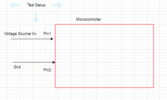
The Red section is a microcontroller and has in built Opamp which will amplify the signal and then connect to ADC (internal to micro). I created the following setup
1679598150309.png
I have connected the power source of certain voltage and not populating the Rshunt and measuring the adc count. Is this proper setup simulating voltage without actually passing current?
 

danadak

Feb 19, 2021
767
Joined
Feb 19, 2021
Messages
767
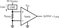
If you only want the Vshunt x G to input to ADC, eg. reject common mode,
then a diff amp is needed.

1679620593328.png

Or you use a processor with a DelSig on it with a differential front end, like this :

1679620545547.png


Regards, Dana.
 

electronicsLearner77

Jul 2, 2015
306
Joined
Jul 2, 2015
Messages
306
My question is different i have all the differential circuit with opamp, i have written the program to initialize the opamp and the ADC and the micro STM32 family. Now i have to test if the current flowing and the ADC value reading are matching or not. I don't have the shunt resistor populated since it is not available now. My question is to the Input1 i provide one voltage say 1.2V and to input 2 i provide 0V and verify the software is it correct method? or i need to mandatorily put shunt resistor and pass current through it and measure ADC count?
 

electronicsLearner77

Jul 2, 2015
306
Joined
Jul 2, 2015
Messages
306
If i do the first method what will be the problem? Can you explain please, since as of now i am not successful in reading the voltage properly ADC count properly. I will finally go to the 2nd method.
 

danadak

Feb 19, 2021
767
Joined
Feb 19, 2021
Messages
767
If i do the first method what will be the problem? Can you explain please, since as of now i am not successful in reading the voltage properly ADC count properly. I will finally go to the 2nd method.

Yes you can just use a supply to gen a fixed V into ADC to check your code is
correct. But be careful you know that V does not exceed datasheet max on the
analog input pin is.

Regards, Dana.
 

electronicsLearner77

Jul 2, 2015
306
Joined
Jul 2, 2015
Messages
306
But one difficult problem is, there is an in built opamp inside the micro, so the voltage I give will pass through opamp with set gain(software programmable) and output of opamp will go to ADC. I will try as suggested.
 

danadak

Feb 19, 2021
767
Joined
Feb 19, 2021
Messages
767
1) What is part number of specific micro you are using ?

2) What is range of current you want to measure ?

3) What is resolution of the current measurement you wish to perform ?

4) What is bandwidth of the current you are trying to measure ?

5) Goal Sample rate of your measurement ?


Regards, Dana.
 

Aliuxama41

Apr 6, 2023
1
Joined
Apr 6, 2023
Messages
1
I planned to test the phase currents i have board which is partially populated, need to confirm if the firmware is reading the currents properly
View attachment 58507
The Red section is a microcontroller and has in built Opamp which will amplify the signal and then connect to ADC (internal to micro). I created the following setup
View attachment 58508
I have connected the power source of certain voltage and not populating the Rshunt and measuring the adc count. Is this proper setup simulating voltage without actually passing current?
Hi,

Based on your description, it seems like you're trying to test the phase currents on a partially populated board with a microcontroller that has a built-in opamp for signal amplification, connected to an internal ADC. However, you mentioned that you have not populated the Rshunt and are measuring the ADC count without passing any actual current.

It's important to note that without the Rshunt being populated, you may not get accurate readings for the phase currents. The Rshunt is typically used to create a voltage drop proportional to the current, allowing for accurate current measurements. Without the Rshunt, there may not be a proper current path, and the ADC readings may not be reliable.

To ensure that your firmware is reading the currents properly, it's recommended to populate the Rshunt according to the board's design and specifications. This will allow the current to flow through the Rshunt, creating a measurable voltage drop that can be accurately amplified by the built-in opamp and measured by the ADC.

For a step-by-step guide on how to test a MOSFET in-circuit, you can refer to https://multimeterworld.com/how-to-test-mosfet-in-circuit-a-step-by-step-guide/. It provides detailed instructions on how to test MOSFETs using a multimeter, ensuring accuracy and safety.

Hope this helps! If you have further questions, feel free to ask.
 

danadak

Feb 19, 2021
767
Joined
Feb 19, 2021
Messages
767
A quick and dirty way is use a JFET like a J109, operate it as current source,
and use a R to develop the V from the current.

See this book, section starting on page 233 for current source application.


OR if you dont have a JFET use a NPN -

1680775995801.png


OR use a LM317 -

1680776081750.png


Regards, Dana.
 
Top