Maker Pro
Maker Pro

Theory/reality mismatch in a transistor circuit

OrangeArav

Jul 14, 2015
38
Joined
Jul 14, 2015
Messages
38
Good Day,

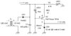
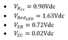
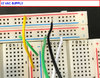
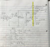
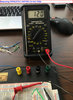
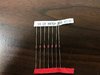
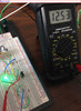
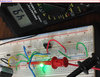
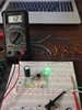
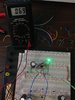
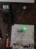
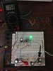
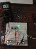
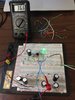
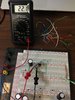
I am having difficulties getting the results as described in the book (attached). My base current is only 2.67mA and collector current is around 30mA. The transistor I am using is MJE2955T, as recommended by the author. Below is a list of measurements I performed with a multimeter:

upload_2018-10-28_2-31-17-png.43577


I don’t understand why is VCE such a small voltage in my situation. I checked my connections and they all look correct. I also have checked the transistor itself and it is functioning properly. Please help resolve this problem. Thank you.
 

Attachments

  • 2018-10-28_012619.jpg
    2018-10-28_012619.jpg
    41.5 KB · Views: 25
  • Elec.pdf
    867.2 KB · Views: 9
  • upload_2018-10-28_2-31-17.png
    upload_2018-10-28_2-31-17.png
    5.7 KB · Views: 106
  • my ckt.jpg
    my ckt.jpg
    389 KB · Views: 18

(*steve*)

¡sǝpodᴉʇuɐ ǝɥʇ ɹɐǝɥd
Moderator
Jan 21, 2010
25,510
Joined
Jan 21, 2010
Messages
25,510
That's an unusual circuit.

You have a simple constant current driver which is supplying around 41mA (VR[sub]22[/sub] / R22).

It is not 50mA chiefly because VRed[sub]LED/sub] varies significantly between LEDs.

In theory, if your supply voltage is 17V and the zener has 12V across it, and R22 has 0.9V across it, then VEC must be 17 - (12 + 0.9) - 4.1V.

There are a couple of things which could cause your error:
  1. The zener is not a 12V device
  2. The input voltage is not 17V (could it be falling under load?)
  3. Your measurement is incorrect.
However, looking at your layout on the breadboard, if the AC is coming in on the two horizontal sections of breadboard, you have wired up the power supply all wrong.
 

OrangeArav

Jul 14, 2015
38
Joined
Jul 14, 2015
Messages
38
*steve* thanks for your response. Attached are also my hand calculations where I got VCE = 4.1Vdc. Also, I took photos of my connection to the source. Please let me know if it is correct.
  1. The zener is not a 12V device. I am using a 1W, 12Vdc, 1N4742A zener diode.
  2. The input voltage is not 17Vac (could it be falling under load?) The input voltage is 12Vac (RMS) * 1.41 ~ 17Vac peak. No load is connected to the output of the zener diode.
  3. Your measurement is incorrect. It could be incorrect; please let me know whether it is correct or not, based on the photos I have provided.
 

Attachments

  • IMG_1034.jpg
    IMG_1034.jpg
    477.1 KB · Views: 7
  • 2018-10-28_161314.jpg
    2018-10-28_161314.jpg
    102.4 KB · Views: 8
  • IMG_1031.jpg
    IMG_1031.jpg
    377 KB · Views: 6
  • IMG_1032.jpg
    IMG_1032.jpg
    325.8 KB · Views: 6
  • IMG_1036.jpg
    IMG_1036.jpg
    359.1 KB · Views: 8
Last edited:

(*steve*)

¡sǝpodᴉʇuɐ ǝɥʇ ɹɐǝɥd
Moderator
Jan 21, 2010
25,510
Joined
Jan 21, 2010
Messages
25,510
This should give you an idea of what you've done wrong. I have reverse engineered your breadboard layout into a schematic:

upload_2018-10-28_15-40-58.png
 

Audioguru

Sep 24, 2016
3,656
Joined
Sep 24, 2016
Messages
3,656
The first photo shows a 1k resistor parallel with two 10k resistors, not three 10k resistors..
The second photo shows a white or bright green LED, then it is not 1.63V, instead it is 3V or 3.2V at the low current.
 

Attachments

  • resistors.png
    resistors.png
    64.3 KB · Views: 8

OrangeArav

Jul 14, 2015
38
Joined
Jul 14, 2015
Messages
38
Thank you all for your responses. *steve*, the circuit you drew has the negative terminal of ‘C1’ ungrounded. However, my ‘C1’ capacitor’s negative terminal is grounded. Is that what you are referring to is wrong with the circuit?

After I corrected my Rbias2 to three 10k ohms in parallel (thanks to Audioguru), I measured my collector current and got about 40mA at a base current of 3.8mA. Is B = 10?

Then, I decided to change my resistance values to 11 ohms for RE2 and 1k ohms for Rbias2 and got about 50mA collector current. The question is – how did the author measured about 50mA collector current at a 4.5mA base current (keeping all components unchanged), whereas I cannot repeat his results. His B = 50 and mine is not?
What exactly does this statement from the book mean- 'Thus, we have 4.5mA available, which is more than enough for the base current requirement of 1mA for providing 50mA of regulated current.'
In my case: I have 3.8mA base current available which is more than enough for a base current requirement of 1mA for providing 50mA of regulated current. In my view this means, in theory, if the base current is 1mA then to get a collector current of 50mA is simply a matter of tuning the resistor RE2 to give you 50mA by dividing voltage drop on RE2 by its resistance...
Please provide suggestions.
 

Attachments

  • Ckt.jpg
    Ckt.jpg
    337.1 KB · Views: 5
Last edited:

Audioguru

Sep 24, 2016
3,656
Joined
Sep 24, 2016
Messages
3,656
How do you know the base current when an unknown current feeds the LED?
Beta is when a transistor is an amplifier with plenty of collector to emitter voltage. Here the transistor is saturated so beta does not apply and the collector current is usually 10 times the base current.
 

(*steve*)

¡sǝpodᴉʇuɐ ǝɥʇ ɹɐǝɥd
Moderator
Jan 21, 2010
25,510
Joined
Jan 21, 2010
Messages
25,510
How do you know the base current when an unknown current feeds the LED?

The base current is what it needs to be. It's almost unimportant in this circuit. As long as there is sufficient current available from the bias network.
 

Audioguru

Sep 24, 2016
3,656
Joined
Sep 24, 2016
Messages
3,656
The base current is what it needs to be. It's almost unimportant in this circuit. As long as there is sufficient current available from the bias network.
Exactly. It probably is not 3.8mA, it depends on the current gain of the transistor when it is saturated and the actual forward voltage of the LED and the tolerance of a few other parts.
 

OrangeArav

Jul 14, 2015
38
Joined
Jul 14, 2015
Messages
38
Hello experts.

(*steve*), you still haven’t provided an answer to my response about the circuit? You wrote something was incorrect; can you please point out exactly what is incorrect?

My confusion is in the biasing circuit. The resistors RE2 and Rbias2 are the biasing resistors that turn the transistor ON, is that correct? In this particular circuit the objective is to reduce AC ripple voltage left after rectification. If there is sufficient base current then collector current is determined by Ic = V_RE2/RE2 and the base current is not important.
Again, I measured my VCE voltage and got about 0.02 V. After I started increasing my supply voltage, I did not see an appreciable increase in VCE voltage. Could you explain what am I doing wrong. Thank you in advance.
I have also attached images where I am repeating base and collector current measurements.
 

Attachments

  • IMG_0089.JPG
    IMG_0089.JPG
    356.2 KB · Views: 1
  • IMG_0091.JPG
    IMG_0091.JPG
    336.1 KB · Views: 1

(*steve*)

¡sǝpodᴉʇuɐ ǝɥʇ ɹɐǝɥd
Moderator
Jan 21, 2010
25,510
Joined
Jan 21, 2010
Messages
25,510
Have you measured the voltage across the DC rail?

i.e. measure between the anode of LED2 and ground. This should be the same as the voltage across C1.

Your "unusual" wiring doesn't make the breadboard layout clear. I would recommend that you place the DC +ve and DC ground rails along the upper and lower bus rails of the breadboard, and turn it 90 degrees so these are running horizontally.

After you've read the DC voltage, measure the zener voltage, the voltage across Red, and the voltage between emitter and collector. Do these voltages, when summed equal the supply voltage?
 

OrangeArav

Jul 14, 2015
38
Joined
Jul 14, 2015
Messages
38
Hi *steve*,

I re-made my circuit per your suggestion (images attached). I have the following measurements:

VSOURCE = 12VAC
VCE = 0.069VDC
VRE2 (22 OHM) = 0.91 VDC
VLED2 (RED LED) = 1.58 VDC
VZD1 (ZENER) = 12.93 VDC

Results show that the sum of voltage equal: ZD1 + VCE + RE2 = 12.93 + 0.069 + 0.91 = 13.909 VDC ~ 14VDC. Please let me know what is wrong with the circuit. Thank you for your help.
 

Attachments

  • SOURCE.JPG
    SOURCE.JPG
    350.8 KB · Views: 4
  • VOLTAGE-BETWEEN-COLLECTOR-AND-EMITTER.jpg
    VOLTAGE-BETWEEN-COLLECTOR-AND-EMITTER.jpg
    305.4 KB · Views: 2
  • VOLTAGE-ON-22-OHM.jpg
    VOLTAGE-ON-22-OHM.jpg
    332.4 KB · Views: 3
  • VOLTAGE-ON-RED-LED.jpg
    VOLTAGE-ON-RED-LED.jpg
    307 KB · Views: 2
  • VOLTAGE-ON-ZENER.jpg
    VOLTAGE-ON-ZENER.jpg
    313.9 KB · Views: 2
  • GEN-LAYOUT01.JPG
    GEN-LAYOUT01.JPG
    322.8 KB · Views: 2
  • GEN-LAYOUT02.JPG
    GEN-LAYOUT02.JPG
    245.1 KB · Views: 3
Last edited:

OrangeArav

Jul 14, 2015
38
Joined
Jul 14, 2015
Messages
38
I don't see that you have measured the DC voltage to the circuit.


And did you actually measure this or infer it?

(*steve*),

I measured voltages between anode of LED2 to ground and between C1 to ground. For both voltages results are 13.92 Vdc (attached). The two voltages are equal because anode of LED2 is directly tied to positive plate of C1; in reference to ground LED2 & C1 voltages are the same. Now, 12VAC which I have measured (in post #12) gets rectified via power diode '1N4002, CR1' and provides a DC voltage of 13.92. The way it looks to me the total DC voltage is around 13.92 Vdc, which also explains the sum of ZD1 + VCE + RE2 = 12.93 + 0.069 + 0.91 = 13.909 VDC. Please correct me if I am wrong.
 

Attachments

  • VOLTAGE-(C1-TO-GND).jpg
    VOLTAGE-(C1-TO-GND).jpg
    285.5 KB · Views: 2
  • VOLTAGE-(LED2-TO-GND).jpg
    VOLTAGE-(LED2-TO-GND).jpg
    292.1 KB · Views: 2

(*steve*)

¡sǝpodᴉʇuɐ ǝɥʇ ɹɐǝɥd
Moderator
Jan 21, 2010
25,510
Joined
Jan 21, 2010
Messages
25,510
Now, 12VAC which I have measured (in post #12)

Is it still 12V under load? or is it falling to around 10.5V?

Assuming it remains close to 12V, the readings you're getting across the DC supply (13.9V) are indicative of the DC voltage varying from around 12.5V to 16V due to the ripple. My back of the envelope calculations suggest it shouldn't vary by more than 2V (so, from 14V to 16V).

It may also be due to a higher current, caused perhaps by the 22Ω resistor being a lower value. The voltage of almost 13V across the zener means either that the current is higher than expected, or the zener has a voltage higher than 12V (they do vary a little). Is it getting hot? It will be getting warm, but us it too hot to keep a grasp on?

Do you have a source of clean 16V (or around that) DC? You could even connect two 9V batteries in series to get 18V. Alternatively (if your power supply is maintaining close to 12V AC) a larger filter capacitor (or a bridge rectifier) will help you.

At the moment there are so many things possibly going wring that I can;t point my finger at just one.

Oh, if you are confident in making current measurements, you could try measuring the current going through the zener diode (by placing the meter in SERIES with the zener) on a current range -- starting with the highest current range your meter has.
 

OrangeArav

Jul 14, 2015
38
Joined
Jul 14, 2015
Messages
38
Is it still 12V under load? or is it falling to around 10.5V?

Assuming it remains close to 12V, the readings you're getting across the DC supply (13.9V) are indicative of the DC voltage varying from around 12.5V to 16V due to the ripple. My back of the envelope calculations suggest it shouldn't vary by more than 2V (so, from 14V to 16V).

It may also be due to a higher current, caused perhaps by the 22Ω resistor being a lower value. The voltage of almost 13V across the zener means either that the current is higher than expected, or the zener has a voltage higher than 12V (they do vary a little). Is it getting hot? It will be getting warm, but us it too hot to keep a grasp on?

Do you have a source of clean 16V (or around that) DC? You could even connect two 9V batteries in series to get 18V. Alternatively (if your power supply is maintaining close to 12V AC) a larger filter capacitor (or a bridge rectifier) will help you.

At the moment there are so many things possibly going wring that I can;t point my finger at just one.

Oh, if you are confident in making current measurements, you could try measuring the current going through the zener diode (by placing the meter in SERIES with the zener) on a current range -- starting with the highest current range your meter has.

Hello *steve*,

Is it still 12V under load? or is it falling to around 10.5V?

Before connecting a 4.7k resistor load, the voltage on ZD1 was 13.03Vdc. After I connected a 4.7k resistor in parallel with ZD1 the voltage on ZD1 fell to 12.97Vdc. I also monitored the voltage on source, 12Vac, and the results were the same before and after connecting the load.

Assuming it remains close to 12V, the readings you're getting across the DC supply (13.9V) are indicative of the DC voltage varying from around 12.5V to 16V due to the ripple. My back of the envelope calculations suggest it shouldn't vary by more than 2V (so, from 14V to 16V).

Steve, teach me please, what are these calculations? I would like to also be smart at making envelope calculations, hah.

It may also be due to a higher current, caused perhaps by the 22Ω resistor being a lower value. The voltage of almost 13V across the zener means either that the current is higher than expected, or the zener has a voltage higher than 12V (they do vary a little). Is it getting hot? It will be getting warm, but us it too hot to keep a grasp on?

The resistance of RE2 is about 22.1 ohms. Yes, the zener is very hot to the touch.

Do you have a source of clean 16V (or around that) DC? You could even connect two 9V batteries in series to get 18V. Alternatively (if your power supply is maintaining close to 12V AC) a larger filter capacitor (or a bridge rectifier) will help you.

If we find a pure DC source, such as a battery, that would defeat the purpose of building this circuit. I also tried connecting two 470uF capacitors in parallel and did not see any difference.

Oh, if you are confident in making current measurements, you could try measuring the current going through the zener diode (by placing the meter in SERIES with the zener) on a current range -- starting with the highest current range your meter has.

Current measured in series with ZD1 is about 36.6 mA. I don’t understand, however, how can this be true because in, theory, current should be I = P/V. If this is a 1W diode, then the current should be 1W/13V = 77 mA. The zener was very hot to the touch but I’m not sure what the difference between 36mA is and 77mA as far as temperature is concerned. Could this be an issue with my meter?
 

Attachments

  • Current-through-ZD1.jpg
    Current-through-ZD1.jpg
    334.9 KB · Views: 1
  • Current-through-ZD1--02.jpg
    Current-through-ZD1--02.jpg
    379.6 KB · Views: 1
  • Drop-in-voltage-(NO-LOAD).jpg
    Drop-in-voltage-(NO-LOAD).jpg
    379 KB · Views: 1
  • Drop-in-voltage-(WITH-LOAD).jpg
    Drop-in-voltage-(WITH-LOAD).jpg
    380 KB · Views: 1
  • Resistance-22-ohm.jpg
    Resistance-22-ohm.jpg
    366.7 KB · Views: 1

BobK

Jan 5, 2010
7,682
Joined
Jan 5, 2010
Messages
7,682
The 1W rating of the zener is a maximim, it does not automatically use 1W. If it is 36.5 mA at 13V, the power is about a half a Watt.

Bob
 

OrangeArav

Jul 14, 2015
38
Joined
Jul 14, 2015
Messages
38
BobK,

What is then the problem with my circuit? It seems like I built the circuit correctly but due to fluctuations in component parameters I have DC supply voltage of about 14Vdc instead of 17Vdc as per the book.I will try increasing the ac supply voltage to see what happens with the collector current.
Another point which might be causing issues is that the ac is not pure; emphasizing a post by (*steve*), if I probably had a full diode bridge rectifier the dc supply could be higher...
 

OrangeArav

Jul 14, 2015
38
Joined
Jul 14, 2015
Messages
38
Could someone help out to understand what is going? Please provide some guidance.
 

(*steve*)

¡sǝpodᴉʇuɐ ǝɥʇ ɹɐǝɥd
Moderator
Jan 21, 2010
25,510
Joined
Jan 21, 2010
Messages
25,510
I suggested you try powering it from a clean DC source, but you refused
 
Top