Maker Pro
Maker Pro

Transistor Help

Reddave101

Mar 10, 2020
35
Joined
Mar 10, 2020
Messages
35
Hi all, I’m in a dilemma. I’ve been working on my 90s stereo fault which causes the screens to dim and stop working and seems to be a common issue with this system but no fix mentioned. I’ve narrowed it down after a couple of weeks of research and testing: I’m looking for transistors. I’m in need of 2 but I’ve searched everywhere I can look to find them and no joy. They are SA935Q Ono voltage transistors. I’ve tried looking for alternatives but can’t seem to even find a alternative. Does anyone by any chance know where it may be possible to find these or even know of an alternative? Any help would be greatly appreciated as now I’m really stuck thanks in advance
 

73's de Edd

Aug 21, 2015
3,622
Joined
Aug 21, 2015
Messages
3,622
Sir Neal . . . . . .

Well then . . . . . why don't you try inserting the OMITTTED numerical 2 prefix to then get yourself a full . . . . . 2SA935Q.

Get that units data sheet . . . . . . being HOT linked just below . . . . . . and you will then find that it is being a TALL cased TO-92 PNP transistor.

https://alltransistors.com/adv/pdfview.php?doc=2sa935.pdf&dire=_transys

Now since you gave us NEITHER a BRAND or its MODEL number !
(BOY! . . . . . ( You must think that we are GOOOOOOOOOD ! . . . . along with inherent clairvoyant capabilities . )
Therefore, I can only surmise that this device is functioning as one of its driver transistors ijn a single audio power output stage.

Look at that data sheet and it tells you in its page 1's final gasp . . . . that the "Q" suffix . . . . is indicative of it being culled out of all of the beta / DC gains encountered and will be falling within the 120-270 spectrum.
Thaaaaasssssit . . . . .

Now . . . .after I posted . . . . .I see a quasi dupe . . . .

73's de Edd . . . . . .

bulb-light.gif
 

Reddave101

Mar 10, 2020
35
Joined
Mar 10, 2020
Messages
35
Thanks for the reply’s. It’s a 90s aiwa separates stereo. I do have schematics and have tested pretty much every cap, diode and resistor on the board and on the circuit in question. And the 2x 2SA935Q pnp voltage transistors have given me very low readings to where they should be and the cap on that circuit is blowing which that circuit runs the 2 screens. Amp screen and tuner screen. I’ll try upload a pic of the schematic to show better. Thanks again
 

Reddave101

Mar 10, 2020
35
Joined
Mar 10, 2020
Messages
35
C114 is the cap that keeps blowing. But what does confuse me is that on that pic it shows c114 is 470/10 but on the parts list it is a 100/10?? And the original one that blew in the amp is 100/10 so have stuck to the 100 but upped voltage to 25 instead of 10. So now in it is 100/25. It’s a 5 piece system and everything stays perfect until I plug the tuner in then the amp display dims and so does the tuner until cap blows after 2-3 mins even when not being used.
 

Attachments

  • 99F5C9CC-F59B-4AE0-A0A0-E0886234ED0C.jpeg
    99F5C9CC-F59B-4AE0-A0A0-E0886234ED0C.jpeg
    308.5 KB · Views: 8

Bluejets

Oct 5, 2014
6,920
Joined
Oct 5, 2014
Messages
6,920
Cap blowing is a sign of either too low a voltage cap or installed a-about.
Presence of any ac too.
 

73's de Edd

Aug 21, 2015
3,622
Joined
Aug 21, 2015
Messages
3,622
Earlier Errata . . . Post # 3 addressee . . . . .should be Reddave101 . . . . . vice esteemed contributor . . . . . Neal

Sir Reddave101 . . . . .


You STILL didn't give the units model number and the only two parts shown on your schema snippet that are being other than solely discrete parts are the DBF60C-K13 FWB part #'s and the OSA-SS-212CM5 relay and EVEN they show up being used in so many other AIWA models, that they are not usable for differentiating for a specific Aiwa model .

Seeing that I had dealings in the past with another AIWA unit . . . I am now using its common relevant info in the interim . . . awaiting for your further model info.

upload_2021-10-14_21-6-18.png

Circuit flow . . . .


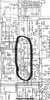
The power transformers raw ~38 V AC initially goes to GREEN A and thru fuse resistor R122 to GREEN B to then be rectified by D103 to yield a NEGATIVE ~52VDC and filtering at PINK C E-cap C113 and its adequate voltage rating of 63V .

So that means to CLOSELY watch the installed polarity of all E-caps and diodes associated with this supply .

At the Q112 transistor, being used as a regulator, you have its base being fed from the resultant voltage being acquired by D105, a 30 v zener diode and via the in line R101 / R102 voltage divider bridge.
That combo results in an ~ NEGATIVE 40 VDC then being present at the emitter of Q112.
That regulated NEGATIVE DC voltage then flows on down the PINK E path to input into Q111 , used as a gyrator/ capacitive multiplier, its base gets a reduced sample of D105 zener reference diode voltage via series inserted R103 and also has C114 filter tied into that PINK F junction.
( Take note that the -29V to -29.6V voltage difference is being well covered with the specified 10V rated cap. )
Transistor conduction lets Q111 emitter - collector have a junction loss and a resultant ~NEGATIVE 29.1 present at Q111 emitter PINK G.
There is then a series inserted 10 ohm current limiting resistor R104 , to then release your regulated ~ NEGATIVE 29VDC suppply into the units shared <-VFL> supply line to feed two other units Vacuum Fluorescent Display type of displays.
If you test out this supply WITHOUT those two other units being connected and find it somewhat normal . . . . less their loading effect on being connected .

ANALYSIS . . . . . of the C114 situation

Then we need to examine their circuitry for what fault they must be causing when then being hooked into this supply.
In looking at the possibility of what would /?/ could cause a "BLOW UP / MAKE- A - BOOM-BOOM " of C114.

Observe that . . . .
The left + terminal of C114 is being directly connected to the <-VFL> supply line or thru a 10 ohm resistor to the emitter of Q111
Pretty much an unbridled, down stream, power path there . . . .

So o o o o o . . . .Observe that . . . . .
The right - terminal of C114 goes two paths, one to R103 4.7k resistor, which at our voltages involved cannot pass enough power to blow C114.
The other path is to the base of Q111 and you also don't get enough power from transistors bases to blow up things connected to it . . .UNLESS . . .
its junction has blown/ fused / melted into the Q111 collector and lets the higher 40V supply line voltage into that C114 E-cap.
So you test Q111 CBE junctions for their conditions..

OR


Now you see why I need this units AIWA model number for its complete /whole schematics for my being able to provide you any further help..

( Ignore the schematics far left side, as that relates to the VFD displays filament supply enabling.)

73's de Edd . . . . .

ZUJ . . . . .Standing by

EatingPopcorn.jpg


.
 
Last edited:

Reddave101

Mar 10, 2020
35
Joined
Mar 10, 2020
Messages
35
Thanks for the useful info and appreciate the time you took writing it. Sorry thought I put the model number. It’s the MX-Z9400M. Thanks again
 

Reddave101

Mar 10, 2020
35
Joined
Mar 10, 2020
Messages
35
Sorry just to mention I’m no electronic expert I’ve had to do a lot of reading to get this far as couldn’t find anyone in my area who could possibly even help with this, so I’ve only got basic knowledge how this works. I’m pretty good with a soldering iron and can replace things that I can see is blown. I’ve tested the Q111 and Q112 and they are the two resistors in mentioned above. From what I’ve read and watched, when I put a multimeter on the BCE I get readings on all of the legs, I’m not getting a neutral from either of them. From my understanding I should get a neutral from one and at least 600 on the others.

On Q111 I get 003 from all legs and on Q112 I get 122 from all legs on the diode setting on multimeter. I did check a new transistor I’ve got lying around(from a hobby box I picked up) and that one does show me 736 and does have a neutral on the same diode setting. Which is what made me believe it’s these that may have failed.

when I changed the C114 initially the two screens light up like a Christmas tree again for a minute or two but then blows again. So upgraded it to 25v instead of 10v and they lasted about 20 mins before fading out again. If I don’t connect the tuner to the amp (TX 9400) then the cap doesn’t blow and the screen on the amp stays on permanently and so do the other units. It’s only the tuner that causes it. From my basic knowledge that circuit I showed is what runs the 2 screens.


Extra information is that I did buy another exact amp to replace it when it blew and the original owner did say his started fading so he disconnected it all and it sat in his attic for a good while. Until I advertised I was looking for one. When I picked it up I the screen was a bit dull so lifted the lid and C114 was badly swollen so I replaced it and it works like new again and has been for a month or so but can’t connect the tuner and it slightly fades the amp screen so left tuner uncoupled until I can figure this out as it is a fault on this particular system as when looking for replacement amp there were many listed with same problem.

I took the original amp apart to test and noticed on the underside on main board that at some point in its life Q111 and Q112 had been replaced due to the bad soldering and were slightly loose which just enforced me thinking that these were the bad apple in the system build.


Sorry to waffle on and hope that all makes sense and really appreciate all the help as this system means a lot to me than you could believe and can’t give up on it thanks again
 

Bluejets

Oct 5, 2014
6,920
Joined
Oct 5, 2014
Messages
6,920
You will not get accurate readings on transistors and many other devices for that matter, while still in circuit.
 

Reddave101

Mar 10, 2020
35
Joined
Mar 10, 2020
Messages
35
It’s a PNP transistor so my understanding is that the N is for neutral (base) and should get a signal on emitter and collector? But never mind which way I put the red and black lead from the multimeter I get a signal on all the legs(diode setting on multimeter) like I say I have tried on a new transistor which is PNP aswell(check make sure I’m checking correctly) And that one is perfect. I only get a good signal on emitter and collector and middle leg is my Neutral. Really sorry if sound stupid basic knowledge
 

73's de Edd

Aug 21, 2015
3,622
Joined
Aug 21, 2015
Messages
3,622
Sir Reddave101 . . . . .

On Q111 I get 003 from all legs and on Q112 I get 122 from all legs on the diode setting on multimeter. I did check a new transistor I’ve got lying around(from a hobby box I picked up) and that one does show me 736 and does have a neutral on the same diode setting. Which is what made me believe it’s these that may have failed.

If now testing as being disconnected and out of circuit transistors the 003 and 122 readings equate as bad transistor internal semiconductor junctions.
Your one 736 reading does tell us of it having a valid base to either /both emitter or collector and that you are using your DVM's DIODE test mode. . . . vice its ohms setting / test mode and that 736 reading is indicative of a developed 736 millivolts reading across that transistor junction then being tested.
Do further tests . . . or retest by . . . . .
Keeping DVM switch position(s) as it was when getting the 736 reading.
Then place one meter lead to the base and keep it there while you take the other meter lead and take a reading when connecting to each of the other transistor leads (emitter and collector). Expect a reading of being 500'ish through 700'ish millivolts for a GOOD base to emitter or collector semiconductor junction of a silicon transistor . . . . which yours are.
Then you reverse lead positions and test again in the same manner, but expect no reading or an OL meter reading . . . . .according to your meters manner of displaying an open circuit.
Then as a final test, if all prior readings are passing, you then test between collector and emitter for having no leakage and then repeat again with the meter leads reversed.

Out of here . . . .will be pulling 9400 schematic now . . . .

73's de Edd . . . . .
 
Last edited:

Reddave101

Mar 10, 2020
35
Joined
Mar 10, 2020
Messages
35
Thankyou, the one I was getting a good reading was a new transistor I have sitting about but is no good for this application. The two I think are bad from the board are giving me far less readings 1 is reading 001-004 regardless which leg you touch with the leads which ever way round you touch them red or black. The other transistor is giving me a 121-123 again which ever way round you touch the legs with the red, black leads. As they are such low numbers and haven’t got a base(neutral) I’m guessing these have shorted?? Both are the same 2SA935Q and like I say I’m assuming I should have readings above 600 on both? But both very low and very different with no neutral thanks again for your time and patience
 

Reddave101

Mar 10, 2020
35
Joined
Mar 10, 2020
Messages
35
Just ordered 4 x 2SB560 transistors fingers crossed these work thanks a lot to all with input
 

Reddave101

Mar 10, 2020
35
Joined
Mar 10, 2020
Messages
35
Well guys an update and now even more confused. I’ve received the transistors and also ordered some bc640 ones aswell. Have put them in the board but now I get no screen on amp or tuner whatsoever? I’ve tested the transistors and following the description making sure I’ve received the correct pnp ones and not npn I’m getting odd results. As follows:

red - middle leg , black 3rd leg =736
Red- middle leg , black 1st leg =0

Black -middle leg, red 3rd leg =0
Black - middle leg , red 1st leg =0

Black - first leg , red 2nd leg =0
Black - first leg , red 3rd leg =0

Red - first leg , black 2nd leg = 0
Red - first leg , black 3rd leg = 784

I hope that makes sense? Can’t figure out if this is correct as since putting these in the circuit no screen whatsoever? Whereas with the broke ones in before the screen came on but then faded out until the cap blew.

many further help is greatly appreciated
 

Reddave101

Mar 10, 2020
35
Joined
Mar 10, 2020
Messages
35
Sorry that what I mean by 1st , 2nd , 3rd leg
 

Attachments

  • 3C016CB8-05C1-4AE2-A280-0380FD8FAA9B.png
    3C016CB8-05C1-4AE2-A280-0380FD8FAA9B.png
    318.6 KB · Views: 3
Top