Evening all,
I am banging my head against the wall with this problem.
What I am trying to do should be very simple - just turn on/off a 12v solenoid with a transistor or MOSFET controlled by my arduino.
I have read at least 50 blog posts or forum threads on this subject, but just cannot find the solution.
My electronics experience - beginner.
I have tried numerous different transistors and MOSFETS, following advice found during my research, but to no avail.
My test circuit -
- 3 Blue LED with resistor.
- 12V adaptor supplying 2A current
- Blink sketch with pin 13 running to appropriate pin on tran/mosfet
- All lead positions treble checked and LED lighting up if supplied power direct.
- Common ground between 12v supply and Arduino
- Tested - TIP31, IRL8113PBF & some other transistors that I can't find at the moment (desk is a bit cluttered)
- Transistor/MOSFET all N series and placed after the LED from the 12v supply
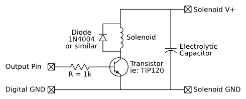
- Circuit is like this but without the capicitor (and with various different components tried:
Problem -
- 90% of the time with transistor/mosfet in position LED simply stay on at what looks to be half brightness, as if there is a power leak getting through the component. They do not Blink though.
- Nearly rest of time LED are either at full brightness (not blinking) or just do not light at all.
- I did get the test circuit to work with the TIP31. The LED flashed on and off as expected but again were at a much lower brightness than I thought they would be. I then switched in my solenoid (which again works when given power directly) which did not work at all.
I have spent a fair bit of money on different components now, all to no avail, and simply can't find the answer. All the problem threads I've read end with the initial poster having their problem resolved but the answers don't work for me.
So, does anyone have any ideas at all?
Even better, and for my eternal gratitude, could someone list the exact parts and circuit diagram I need to follow to get this to work? The solenoid I need to get to work is this one - http://www.ebay.co.uk/itm/251488508604?_trksid=p2060778.m2749.l2649&ssPageName=STRK:MEBIDX:IT
Many, many thanks indeed in advance.
Have a great day!
Smirks
I am banging my head against the wall with this problem.
What I am trying to do should be very simple - just turn on/off a 12v solenoid with a transistor or MOSFET controlled by my arduino.
I have read at least 50 blog posts or forum threads on this subject, but just cannot find the solution.
My electronics experience - beginner.
I have tried numerous different transistors and MOSFETS, following advice found during my research, but to no avail.
My test circuit -
- 3 Blue LED with resistor.
- 12V adaptor supplying 2A current
- Blink sketch with pin 13 running to appropriate pin on tran/mosfet
- All lead positions treble checked and LED lighting up if supplied power direct.
- Common ground between 12v supply and Arduino
- Tested - TIP31, IRL8113PBF & some other transistors that I can't find at the moment (desk is a bit cluttered)
- Transistor/MOSFET all N series and placed after the LED from the 12v supply
- Circuit is like this but without the capicitor (and with various different components tried:
Problem -
- 90% of the time with transistor/mosfet in position LED simply stay on at what looks to be half brightness, as if there is a power leak getting through the component. They do not Blink though.
- Nearly rest of time LED are either at full brightness (not blinking) or just do not light at all.
- I did get the test circuit to work with the TIP31. The LED flashed on and off as expected but again were at a much lower brightness than I thought they would be. I then switched in my solenoid (which again works when given power directly) which did not work at all.
I have spent a fair bit of money on different components now, all to no avail, and simply can't find the answer. All the problem threads I've read end with the initial poster having their problem resolved but the answers don't work for me.
So, does anyone have any ideas at all?
Even better, and for my eternal gratitude, could someone list the exact parts and circuit diagram I need to follow to get this to work? The solenoid I need to get to work is this one - http://www.ebay.co.uk/itm/251488508604?_trksid=p2060778.m2749.l2649&ssPageName=STRK:MEBIDX:IT
Many, many thanks indeed in advance.
Have a great day!
Smirks