Hi I'm connecting a Pololu 36V15 motor driver (https://www.pololu.com/product/760) to a motor.
On the left side of the board, we connect the OUTA and OUTB pins to the actual motor, and the V+ and GND go to our power supply.
I have a question on the V+ pin on the logic side of the board (right side in the below image).
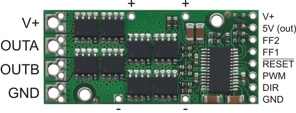
On the right logic side, the description on the pololu website says "the smaller V+ pad on the logic side of the board gives you access to monitor the motor’s power supply (it should not be used for high current)."
I was originally inputting 5V into that right-side V+ pin since I assumed that was needed to power the logic side of the board.
But now I'm not sure if I actually did something very wrong here. Am I not supposed to *input* power into the logic side V+ pin? Is that only meant for reading the motor's voltage as an output?
What is the correct interpretation of the logic-side V+ pin?
And if I'm doing this wrong and you're not supposed to input anything into the right-side V+ pin, then how do the chips on this board get powered? (since I'm assuming the big V+ input on the left side would be too much for the chips since I'm connecting a 24V power supply to drive the motor on the left side)
Thanks.
On the left side of the board, we connect the OUTA and OUTB pins to the actual motor, and the V+ and GND go to our power supply.
I have a question on the V+ pin on the logic side of the board (right side in the below image).
On the right logic side, the description on the pololu website says "the smaller V+ pad on the logic side of the board gives you access to monitor the motor’s power supply (it should not be used for high current)."
I was originally inputting 5V into that right-side V+ pin since I assumed that was needed to power the logic side of the board.
But now I'm not sure if I actually did something very wrong here. Am I not supposed to *input* power into the logic side V+ pin? Is that only meant for reading the motor's voltage as an output?
What is the correct interpretation of the logic-side V+ pin?
And if I'm doing this wrong and you're not supposed to input anything into the right-side V+ pin, then how do the chips on this board get powered? (since I'm assuming the big V+ input on the left side would be too much for the chips since I'm connecting a 24V power supply to drive the motor on the left side)
Thanks.


")

