.
Sir Frank Tank . . . . . . .
Post Addenda . . . . . .Initially poked up on laptop, earlier, prior to 2 added comments . . . . just had to get back to civilization for my image generation and its add on to post.
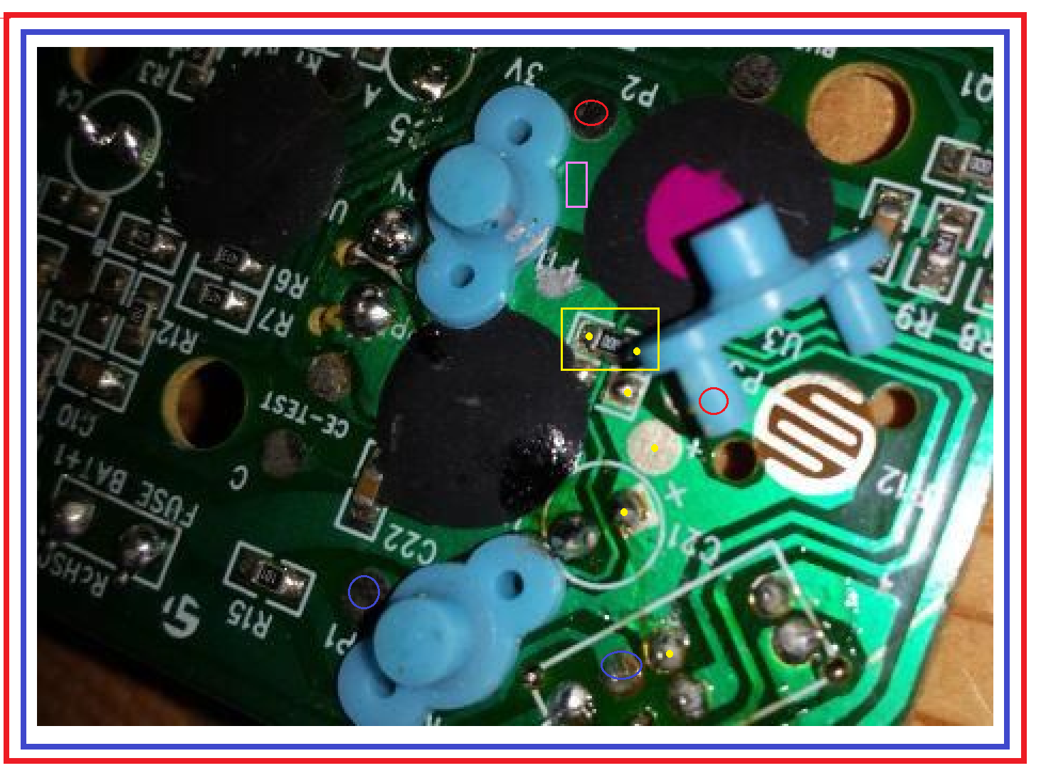
GOOD JOB . . .on the photos ! . . .now I won't have to expound upon the fixed serpentine gold flashed grid switch contacts and the imbedded colloidal graphite pressure contact within the blue switch "buttton"
MARK UP :
Look and you will see C21 electrolytic relevant to power supply filtering and its + terminal foil path goes right up to being 1 common connection of your now exposed switch.
ALSO it goes down and does the same thing to one of your bottom left PB switches.
Then move to the top left PB switch and see that they have opened that buss and made a path for a fine hairline trace to pass thru it (YELLOW rectangle position) HOWEVER they bridged that gap on the top with a
000 ohm resistor (jumper) .
Sooooooo that area will account for three common connections to that circuitry, which would only need one wire to remote then out to a different point and then branch out again..
That one connection could be made to any of the 5 YELLOW dots I have shown or even to the gold test pad just above the + marker of C21 , if you tin it..
On my RED circle, I believe that your PB switch top is hiding an existing solder blob that connects to the other contact of that switch.
On the top PB I believe that my RED circle there is noting an existing solder blob to that other PB switch contact point . If not the FUCSIA rectangle shows room to scrape down to bare copper and make a solder pad.
Bottom left PB, see if one of my BLUE circles . . .at solder blobs . . . . are connecting in to the other contact of that PB switch.
If all are confirmed . . .as same contacts . . .put a drop of rosin flux atop the involved solder blobs and then add a drop of new solder to reflow and "freshen" the joints.
Since the foil side of the board is to be re mounted and then becomes all covered up, my probable procedure, if this being my project , would be to use fine insulated "magnet" wire in the vicinity of 30 gauge..
You scrape a 1/8 inch end to bare copper and use rosin flux to pre tin it. Use a very pointy WELL TINNED soldering iron tip and place the tinned wire tip to the already prepped solder droplet joint and
melt to reflow the solder junction.
Repeat on all of the 3 other connection points and then selectively feed the wires to the other side of the board via the same closest 2 holes that each of the pushbuttons two side "tits" are using for their retention.
The small diameter of the wire along with the "tits" partial compression should accommodate both within the same hole .
Gather your now remoted 3 switch contacts wires, along with the one common of all 3, and interface to a connector and wiring to branch out and interface to the size and type of wiring that you are used to using.
Thassssit . . . . .
73's de Edd


") I appreciate the help
I appreciate the help