Maker Pro
Maker Pro

Trying to get laser sensor to activate jqc-3ff-s-z relay coil

tshaftel191

Sep 18, 2020
8
Joined
Sep 18, 2020
Messages
8
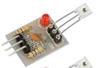
I'm trying to get a laser sensor to trigger a JQC-3FF-S-Z relay. The sensor is this little guy:
upload_2020-10-3_21-35-57.png
It can be found by googling "Icstation 5V Light Sensor Module Receive".

The JQC-3FF-S-Z relay can be also be easily googled:
upload_2020-10-3_21-54-49.png

I have it wired thusly per my understanding of schematics found for both the units:
sensor VCC and relay DC+ connected to power supply 5v positive
sensor GND and relay DC- connected to power supply 5v negative
sensor OUT connected to relay IN
relay jumper is set to honor a high signal (5v in this case)
relay secondary COM and NO are used to complete a 120v circuit upon activation

For the power supply I am using a USB 3.0 5vdc 2.1 amp cell phone charger.

With just the relay connected (DC+ and DC- to power supply) I can trigger the relay by jumpering DC+ and IN and run the 120v circuit.

With all connections as above except the sensor OUT-relay IN connection, 5v+ appears at sensor OUT when the sensor is hit with a red laser. I assumed this would be sufficient to trigger the coil when wired to relay IN.

With all connections as above, when the sensor is lasered the relay's secondary (triggered) led goes on but the coil does not activate. (I should note that both the sensor and my version of the relay have leds that do turn on when the units are powered on. The relay also has the second led that goes on when a signal appears at IN.

Am I misunderstanding how this should work? Does the sensor not produce enough current to power the coil? I have five each of the sensors and relays and have tried several combinations with no success, so I don't think it's a bad unit...unless my wiring is breaking them haha.

Though I have messed around with this sort of thing now and then my whole life, I'm not an electronics expert by any means, and would be grateful for any assistance.
 

Attachments

  • upload_2020-10-3_21-33-57.png
    upload_2020-10-3_21-33-57.png
    30.4 KB · Views: 3

Bluejets

Oct 5, 2014
6,922
Joined
Oct 5, 2014
Messages
6,922
For the power supply I am using a USB 3.0 5vdc 2.1 amp cell phone charger.

From Amazon link......... "Too high input voltage, unstable power supply, reversed polarity will damage the sensor board."

Might be one aspect to consider.
 

tshaftel191

Sep 18, 2020
8
Joined
Sep 18, 2020
Messages
8
Yes, it occurred to me that the power supply might not be smooth or gentle enough. But it was an obvious solution, at least to a rank amateur. Maybe I should test again with a battery pack.

The schematics, of course, sorry. For the light sensor:
upload_2020-10-4_7-26-3.png
For the relay, no schematic but ample instructions:

Module Description:
The module uses genuine quality relay, normally open interfaces
Maximum load: AC 250V/10A, DC 30V/10A
SMD optocoupler isolation, strong driving ability, stable performance; trigger current 5mA
The module voltage 5V
The module can be set high or low triggered by jumper
Fault-tolerant design, even if the control line is broken, the relay will not operate
Power indicator (green), relay state indicator (red)
Interface design user-friendly, all interfaces are available through the wiring terminal direct connection leads, very convenient
Module size: 50mm * 26mm * 18.5mm (L * W * H)
4 mounting bolts holes, hole 3.1mm, 44.5mm * 20.5mm spacing

Module interface
DC +: positive power supply (voltage by relay requirements, 5V.9V.12V and 24V selection)
DC-: negative one
IN: can be high or low level control relay

Relay outputs
NO: normally open relay interfaces, relay before hanging, pull back and COM short-circuited
COM: Relay Common Interface
NC: normally closed relay interfaces, relay and COM short-circuited before, after the pull-vacan
 

Harald Kapp

Moderator
Moderator
Nov 17, 2011
13,722
Joined
Nov 17, 2011
Messages
13,722
trigger current 5mA
This may be the catch. Can the sensor deliver 5 mA or more? The relay module shown in the image seems to have built-in transistors to amplify a weak input signal (or to reduce the input current). Your module has an optocoupler instead requiring 5 mA or more.
What is the voltage on sensor-out when connected to the relay module and sensor is triggered? Does it go up to 5 V?
 

bertus

Moderator
Nov 8, 2019
3,325
Joined
Nov 8, 2019
Messages
3,325
Hello,

An other catch could be that the sensor is open collector.
In that case you must use a pull-up resistor.

Bertus
 

tshaftel191

Sep 18, 2020
8
Joined
Sep 18, 2020
Messages
8
Thanks kindly for the responses.

>What is the voltage on sensor-out when connected to the relay module and sensor is triggered? Does it go up to 5 V?<


Ah. No, it only goes up to 1.94 volts. So the issue could be not enough power to trip the relay? What are possible solutions to that, in the realm of cheap purchase or easy enough to build by one barely knowledgeable but able to follow a schematic that has component values?

>An other catch could be that the sensor is open collector. In that case you must use a pull-up resistor.<


I did a bit of reading on pull-up resistors but so far have only come across examples where it was used to maintain logic 1 high voltage until such time as logic 0 was signalled, which would seem to be the reverse of what I have here. So not sure I can just blindly use what I found.

Disclosure: I didn't rewire it to use a battery pack instead of the 5v cell phone charger to power the trigger circuit, so the possibility of interference from dirty power has not been ruled out. My "breadboarding" capabilities are very rudimentary (alligator clip jumper wires) though if I keep at this I'll up them.
 

bertus

Moderator
Nov 8, 2019
3,325
Joined
Nov 8, 2019
Messages
3,325
Hello,

On the amazon page from icstation:
https://www.amazon.com/Icstation-5V-Laser-Sensor-Module/dp/B01M8PFZRC

5V Laser Recevier Sensor Board work with Arduino
Icstation 5V laser sensor board outputs high level when it receives light, otherwise it outputs low level.

This laser recevier is a NON-MODULATED laser sensor so it is very sensitive to ambient light.
Sunlight and other lights will interfere with its normal operation.
Please keep the sensor in dark environment.

What is the output level when the sensor is fully covered?

Bertus
 

tshaftel191

Sep 18, 2020
8
Joined
Sep 18, 2020
Messages
8
By closing the garage doors and turning off the lights I am able to reduce sensor output down to a few millivolts. When lasered the output rises to 5v (disconnected from the relay) but only a bit less than 2v when connected to the relay which is not enough to activate the relay coil.
 

tshaftel191

Sep 18, 2020
8
Joined
Sep 18, 2020
Messages
8
Correction: haven't paid lots of attention to the exact reading when darkened, but my voltmeter switches to its millivolt range and the value jumps around. Considerably lower than a volt in any case.
 

bertus

Moderator
Nov 8, 2019
3,325
Joined
Nov 8, 2019
Messages
3,325
Hello,

It looks like the sensor can not provide enough current to activate the relayboard.
There must be some kind of booster be installed to have the sensor activate the relayboard.

Do you have more info on the relayboard?
The number you gave is the actual relays and not the board.

This is the closest I could find:
https://www.tinytronics.nl/shop/en/others/relay/5v-relay-1-channel-high-active-or-low-active

It states an input current of 5 mA for the optocoupler.

Bertus
 

Alec_t

Jul 7, 2015
3,590
Joined
Jul 7, 2015
Messages
3,590
Try adding a pull-up resistor (e.g. 1k-10k) between +5V and the sensor output.
 

tshaftel191

Sep 18, 2020
8
Joined
Sep 18, 2020
Messages
8
I hope it's okay to link to the amazon page I bought the relay module from:
https://smile.amazon.com/gp/product/B079FJSYGY/ref=ppx_yo_dt_b_asin_title_o02_s00?ie=UTF8&th=1

There is another block of information on that page, near the top, which I assume is for the whole unit not just the relay portion:
  • The module uses genuine quality relay, normally open interfaces
  • Maximum load: AC 250V/10A, DC 30V/10A
  • SMD optocoupler isolation, strong driving ability, stable performance; trigger current 5mA
  • The module voltage 5V
  • The module can be set high or low triggered by jumper
FWIW, I understand this to mean the IN signal must be able to supply a high voltage with at least 5ma.

That's all the information I could find. Searching for JQC-3FF-S-Z returns hits on the relay cube, not on this relay module that presumab ly uses it.
 

tshaftel191

Sep 18, 2020
8
Joined
Sep 18, 2020
Messages
8
>Try adding a pull-up resistor (e.g. 1k-10k) between +5V and the sensor output.<

Thanks, I'll do that after lunch and report back.
 

tshaftel191

Sep 18, 2020
8
Joined
Sep 18, 2020
Messages
8
Success!!!

With what I had lying around, I first tried a 3.9k resistor but that put too much juice on and the relay activated with no laser. Then tried a 15k resistor and with the garage half-darkened (there was still light coming in windows) the relay triggered when the sensor was hit with the laser. Great...but it stayed on when I stopped lasering. So, not enough ambient light to trigger but enough to latch it on. With it latched, I then covered the sensor with a cup and the relay unlatched.

I then covered a baby food jar with black electrical tape except for a little spot to shine the laser through, covered the sensor with the jar, and it worked exactly as it should--laser on, relay on, laser off, relay off.

Thank you bertus and alec_t for the pull-up resistor idea. And to everyone else for expanding my awareness of how this all works.
 
Top