Maker Pro
Maker Pro

Voltage regulator problem !!

Omar wahbi

Jun 23, 2018
2
Joined
Jun 23, 2018
Messages
2
CD8D7E3B-9B4F-401A-A1D4-DEF55CBBBB8F.jpeg FD6F601A-245B-40CF-B589-F17BF9E2C887.jpeg 3C381C28-F73E-4EA9-A66F-FEE78FFD2F02.jpeg FE851ED5-E5C8-4E90-B8A8-238A753DEA7A.jpeg

Hello everyone i have 3000w voltage regulator that have input range of 120-250v
With output 220v
My problem is the device will show “overvoltage” light after working just a few minutes and will cut off the output current even though the input volatge is nearly 220 so it’s in the range and not even near the over volatge governor.
What can i do to solve the problem? Can i disable the over voltage governor from the electronic board?

Please help...

[Mod edit: removed multiple copies of images]
 
Last edited by a moderator:

Chemelec

Jul 12, 2016
291
Joined
Jul 12, 2016
Messages
291
Sounds like a Parts is Overheating and Changing Value.
Possibly use a "COLD Spray" to find that part and than replace it.
 

kellys_eye

Jun 25, 2010
6,514
Joined
Jun 25, 2010
Messages
6,514
Can i disable the over voltage governor from the electronic board?
Only if you want to destroy any connected equipment.......

If you have (or can find) the schematic you need to look for the part of the circuitry that does the comparison check (with whatever it uses for a reference value) to see if anything has been 'knocked' out of tolerance.

The (one of four) preset resistors along the edge of the board may well be there to calibrate the settings for 'over', 'under' etc etc but without the details you could 'play' with them (don't have anything valuable connected to the output whilst doing this) to see if you can adjust the error out.

<edit> yes, a close up look at the board shows the IC's to be the ubiquitous LM324 - a multi-package comparator device which indicates that the circuit is simply a load of 'window comparators' with band-gap settings to switch in the=ose relays that then select tappings on the transformer.

The preset(s) WILL adjust these settings but you need to confirm that the SUPPLY VOLTAGE TO THE CIRCUIT BOARD is within tolerance first as it may have drifted and affected all the comparator settings.
 

Omar wahbi

Jun 23, 2018
2
Joined
Jun 23, 2018
Messages
2
Only if you want to destroy any connected equipment.......

If you have (or can find) the schematic you need to look for the part of the circuitry that does the comparison check (with whatever it uses for a reference value) to see if anything has been 'knocked' out of tolerance.

The (one of four) preset resistors along the edge of the board may well be there to calibrate the settings for 'over', 'under' etc etc but without the details you could 'play' with them (don't have anything valuable connected to the output whilst doing this) to see if you can adjust the error out.

<edit> yes, a close up look at the board shows the IC's to be the ubiquitous LM324 - a multi-package comparator device which indicates that the circuit is simply a load of 'window comparators' with band-gap settings to switch in the=ose relays that then select tappings on the transformer.

The preset(s) WILL adjust these settings but you need to confirm that the SUPPLY VOLTAGE TO THE CIRCUIT BOARD is within tolerance first as it may have drifted and affected all the comparator settings.
Well many thanks to you i played with the resistors and it seems to be solved the problem so far its output is a steady 228v so i leave it that way and shouldn’t play with anything else right ?
 

73's de Edd

Aug 21, 2015
3,622
Joined
Aug 21, 2015
Messages
3,622
Sir Omar wahbi . . . .

First take a 2,5 cm brush and water and detergent and give the board a thorough scrub from top to bottom to preclude humidity plus the present dust trails causing a conductive mud path between any high voltage and the sensing circuitry over to the right.
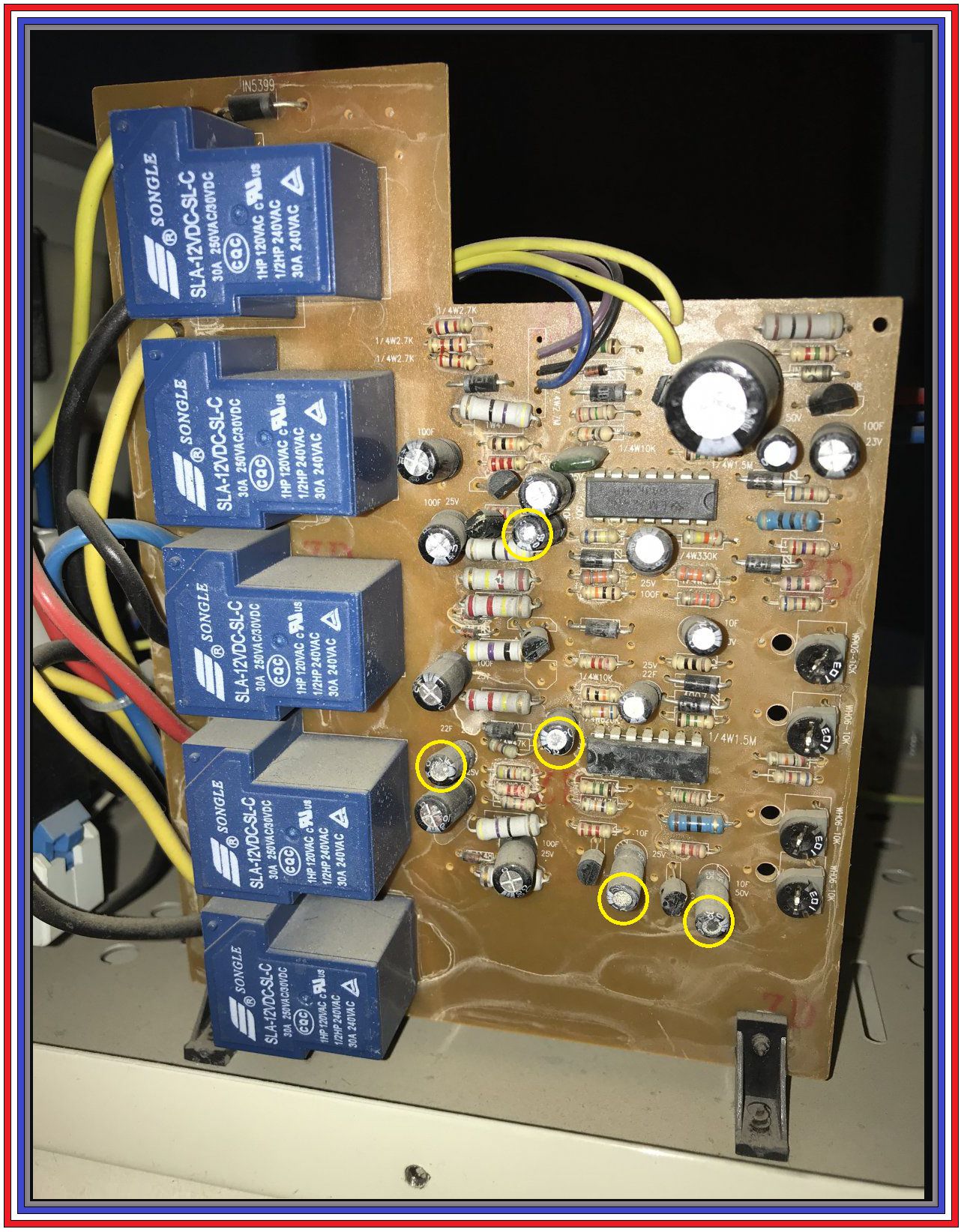
Circuitry design appears to be using zeners and the two quad LM324IC's as comparators to accordingly switch in the power blue relays to the left, to let them then switch AC tapped voltage levels from the power transformer.
The immediate fault response you are now experiencing could be attributed to that type of mud path fault . . . now or in the future .
ORRRRRRRR . . . .it is likely be attributable to a DECLINED time constant in the comparator circuits due to capacitance loss by severe decline of the electrolytic capacitors.
Of particular note are being the YELLOW circled units. (Look at their tops, for one fault aspect)
Some of them, now, might now only be microfarads or nanofarads instead of their previous 10--22 or 100 ufd values.
THEREFORE the resultant "hair trigger " effect on the units sensing ability.

Before cleaning use a permanent SHARPIE pen to mark both rotational parts of each of the pots.
If you have it, start with compressed air cleaning . . . but not at 150 PSI and blowing components right off the board.
Clean the unit as it stands so that runoff water flows straight down and avoids the relays and the pots to the right.
Then a clear water rinse possibly 2 times and then a final forced / heated air speed drying.
Then do a mark up of the pots POSITIONS / or / both resistances, to be reset to, and then a final cleaning of the pots with a solvent and add on of a dielectric protective grease.

MARK UP . . . . . .

VuFGmpv.jpg


73's de Edd
.....
 
Last edited:
Top