This is the design guidelines for aluminium core circuits, want to know more PCB design guidelines,contact us!
Content | Content |
|---|
Content | Content |
What is ‘’Aluminum Board”?
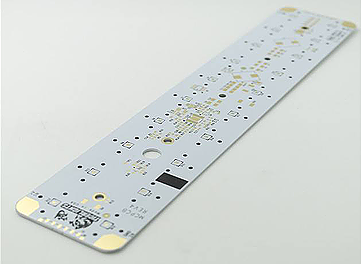
Aluminum PCB is the most common type of all Metal Core PCB (MCPCB) also known as IMS (Isolated Metal Substrate). Aluminum Board are a unique metal-based copper clad laminate excellent thermal conductivity, high mechanical strength and dimension stability.
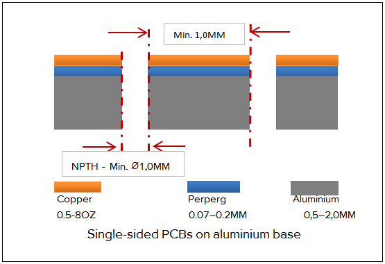
Single-sided PCBs on aluminium base
A copper foil is laminated onto an aluminium base using a prepreg.
Normally, this variant only has drill holes for fastenings.
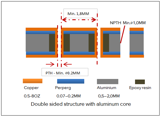
Double sided structure with aluminum core
Copper foils are laminated onto both sides of an aluminium core using prepreg. The PCB can be through-plated.
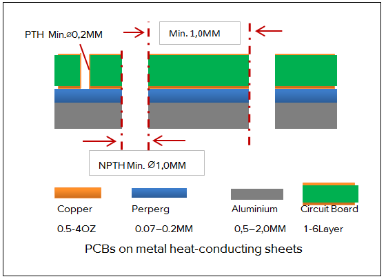
PCBs on metal heat-conducting sheets
Completed PCBs are press-moulded to an aluminium carrier using a prepreg. Benefit: Multilayers can also be used (only single-sided SMD). Disadvantage: Poor heat dissipation, as the heat has to be dissipated through the entire PCB.
Technical data

  • Thickness of the aluminium core: 0,5–2,0 mm
  • Copper thickness: 0.5OZ–8OZ
  • Thermal conductivity:  Standard materials: 1-3W/m.k, Specified materials : 4-12W/m.k
  • minimum drill hole diameter PCB (PTH): ≥ 0,2 mm
  • minimum drill hole diameter PCB (NPTH): ≥ 1,0 mm
  • minimum drill hole diameter for aluminium: ≥ 1,0mm
  • Min distance Drill to Drill: > 1,0 mm
  • minimum router diameter: ≥ 1,6 mm
  • Surfaces: HAL, HAL free lead, OSP, ENIG (not recommended!)
  • Machining:Produced like standard PCBs in multiples or individually, as well as being milled and scored.
If any other questions, you can send emails to [email protected] and tell us what you want to know.