How to build a crude mechanical television, which was the world’s first TV technology.
Whether it be our favorite film or just binge-watching a series, you can bet that a display is involved. While computer monitors are becoming the most used display device, many still use TVs. But the first TV created was nothing like you could possibly imagine. In this DIY hacking project, I will show you how to build a crude mechanical TV, the world’s first TV technology!
Image Controller Circuit
PWM Motor Control Circuit
Mechanical Parts
- Nipkow Disc – You can make your own one using cardboard or PCB material
- Wood
- Glue
- White plastic bag material (for diffusing light)
How Does the Mechanical TV Work?
To understand how the TV works we will split the TV into two main areas; the circuitry that generates the image data, and the mechanical action that turns the image data into a picture. Considering how the TV works, it is best to start with the mechanical theory as the circuitry is designed around that.
The most important mechanical device in the TV is the Nipkow disc, which is a disc that has small holes which spiral inward. Images on TVs typically consists of many horizontal scan lines where images are displayed line by line. On CRT TVs, this scanning technique is rather easy to do with an electron beam which is directed via magnetic fields. In a mechanical TV, this scanline action is done with a Nipkow disc. A small portion of the disc is used as the TV display and as the disc spins there are holes that move across the TV display and this hole scanning action starts at the top of the display and eventually moves down to the bottom of the display. Generating an image is then a matter of using a bright light and turning it on and off at the precise moment. However, timing with a Nipkow disc TV can be tricky which is why early mechanical TVs had issues with synchronizing. Luckily for us, we have microcontrollers and semiconductors which can be used to create all the timing signals for generating images properly!
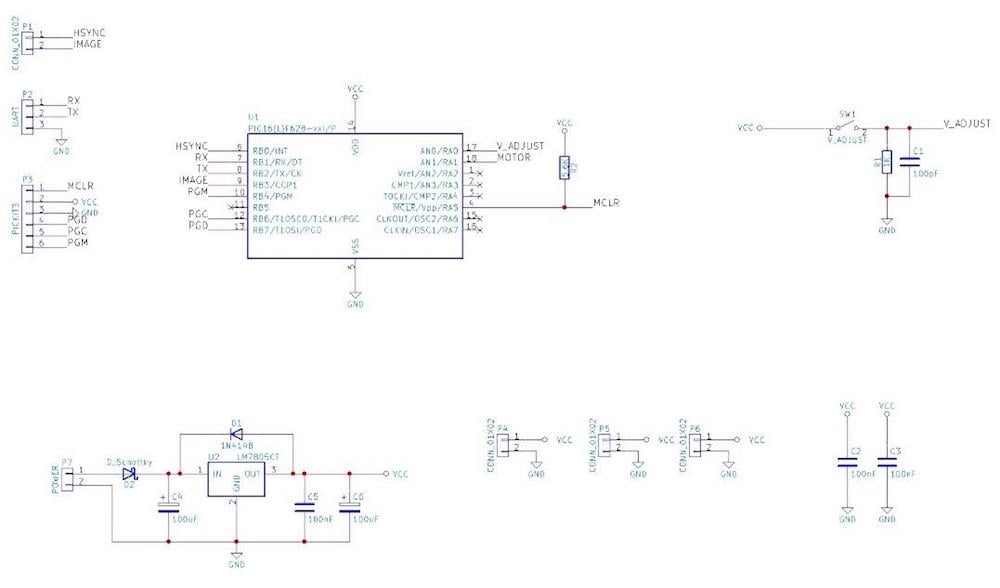
The TV in this project has three main circuits; the motor control, image generator, and a synchronizer circuit. The first circuit, the motor control, is a 555 PWM astable oscillator that helps to keep the disc spinning at a constant speed (variable speeds distort the image). The PWM adjust is done with the 10K potentiometer and the two diodes D1 and D2. The charge time for C2 is dependent on D2 and the resistance of the potentiometer between C2 and D2 while the discharge time is dependent on D1 and the resistance of the potentiometer between D1 and C2.
The image data is generated by the PIC16F628. Upon receiving a HSYNC signal from the TV (discussed later), the PIC code will take a byte of data image (which represents the entire line), and stream the data out bit by bit on the IMAGE pin (RB3 in our case). The only problem with synchronization that this circuit has is that there is no VSYNC signal which informs that the TV has completed one revolution. This means that imaged formed could be in the wrong place vertically on the screen. This is combatted by providing the viewer with a switch that allows the imaged to be shifted down when pressed. This is continuously pressed until the image appears in the correct vertical position.
The last circuit, the HSYNC generator, has two different circuits; one for generating the HSYNC signal for the microcontroller, and an LED driver for driving the white LED that produces the image itself. The HSYNC generator works by using an IR LED and IR Diode that sits on opposite sides of the Nipkow disc. On the disc, there is a ring of holes close to the center that match up with the scan line holes and so when the IR diode detects the IR LED, a new line of image data needs to be displayed. The IR diode produces pulses which are coupled via C1 (to remove DC offsets), and then amplified by U1A. D3 is very important as negative going signals can make the op-amp behave unexpectedly and so D3 removes negative voltages from input signals. This amplified IR pulse signal is then fed into a Schmitt trigger (U1B) to ensure that the output HSYNC signal is clean and only switches when big changes in signals have been detected. The image driver is just two op-amp buffers connected with U2B providing the current needed to drive the LED and U2A being used as an input buffer.
Construction
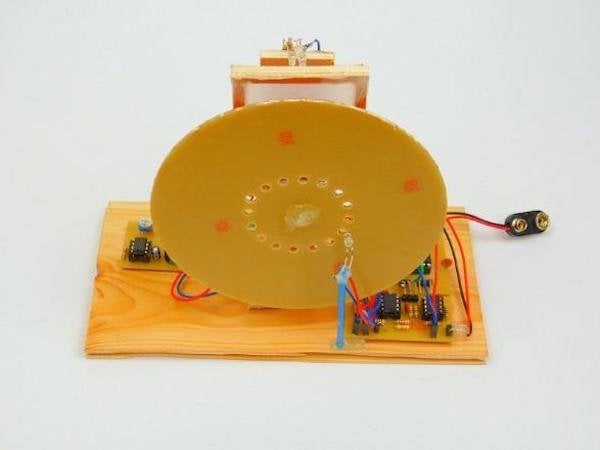
Constructing the TV is very simple with the only mechanical connection being the Nipkow disc and the small motor. The circuits shown here are all built on custom PCBs and a few components are not actually fitted to the PCB. The IR LED / Diode pair need to be fitted so that they are on opposite sides of the disk facing each other where the HSYNC holes are (see the image below).
The image LED (in my case, three small white LEDs), is mounted far back from the disc and a small diffuser is placed between the LEDs and the disc as to create a uniform smooth light. The transistor that drives the motor is not mounted on the PCB (for convenience) and the main controller (along with the HSYNC generator), is located on the opposite side.
Building the Nipkow disc can be done using either cardboard or blank PCB material. The project files given here provide a PCB file that contains the Nipkow disc designs which can be made on a CNC or by hand. The disc must be opaque and have 16 holes that spiral inward with each hole being 1mm and a drop of 1mm such that if one hole is 10mm from the edge then the next hole is 11mm from the disc. You can read more about Nipkow discs here. Using the code example given with the attached project files, you should expect to see an image as shown below. This image can be changed by adjusting the register values found in setup.inc under the image table routine. Be sure to check out the project files at the bottom of this tutorial if you'd like to build your own! Happy making!