Make a laser tripwire system with a key code system to prevent unauthorized disabling and enabling of the alarm.
Home defense can be accomplished with different security technologies such as PIR and sound detection. However, one of the most famous (and probably most devious) devices is the laser tripwire.
In this DIY project, we will make a laser tripwire system that also includes a key code system to prevent unauthorized disabling and enabling of the alarm.
Laser Tripwire Schematic
How the Laser Tripwire Works
Like most PIC projects, the circuitry for the laser tripwire is very basic, with the complexity of this project being the PIC program, itself.
The laser and buzzer in this circuit are controlled by the PIC via a transistor, as PICs are not able to source or sink large amounts of current. Therefore, the transistors Q1 and Q2 act like switches and can enable/disable power to their respective load. Voltage regulation is provided by the LM7805, and various passive components ensure decoupling, pulling up/down logic lines, and reverse polarity protection.
The switch matrix uses four rows of four switches, making a total of 16 switches. If each switch was connected to its own IO pin on the PIC, 16 IO pins would be needed, which is not entirely desirable. However, by using a matrix where four switches are connected together with a 4-bit output, you only need eight IO pins instead of 16.
The downside is that you have to scan through each row as all four buttons on each row share a common bus. Thankfully, this is a PIC and so such a scanning technique is incredibly easy in code, especially C!
The code for the PIC is rather simple, with the following key features:
- Password protection
- Armed or reset state
- Laser trigger detection
- Key detection
The first check that is made in the main program loop is if the security system is in the armed state. If it is, then the analog pin RA0 is read to see if the LDR has sufficient light falling on it (from the laser). If it does not, then the buzzer is sounded. For the sake of simplicity, the code also turns off the buzzer if the light level goes beyond the trigger level. However, a real alarm would not disable the buzzer until the reset code was entered.
The second check is the key scanning system. This is done by first writing 0b00010000 to LATC, which enables the first row. The data from this row is read into a buffer and then LATC is shifted once left. This selects the next row, as LATC would now be 0b00100000 and the data from the matrix is read in.
Eventually, all rows have been read in, which brings us to the next part—the key checks. Switch statements are used for each 4-bit value read-in to determine the key that was pressed. If the key is a number key (0 – 9), then that value is loaded into key buffer, which holds the combination entered by the user. If the key is a function key, then one of the following happens as a result:
- ARM – Enter arm state. Push this first, then enter the password, and then press enter.
- RES – Enter reset state. Push this first, then enter the password, and then press enter.
- CLR – Clears the entered password.
- ENT – Submits the entered password. Will either arm or reset the alarm if the password is valid.
Construction
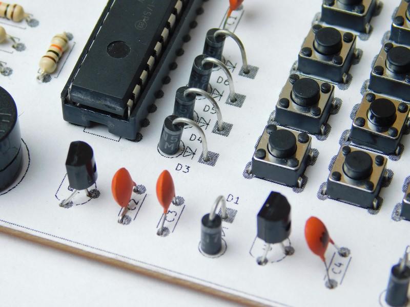
This project uses only through-hole parts, which makes it ideal for most construction techniques, including breadboard, stripboard, matrixboard, and even PCBs. For ease of construction, I have designed this project on a PCB using a CNC milling station. All the CNC files, schematics, and code can be found in the project files below.
The laser grid is set up using mirrors, which are placed in such a way that the laser beam eventually comes back to the LDR. This is highly advantageous for several reasons.
First, it can give you a virtually infinite area of coverage, so long as your beam is powerful enough.
Second, if someone tries fooling your system by shining a flashlight onto the mirror and then crossing the beam, the system will still trigger. A flashlight's beam is too diffused, and by the time the reflection gets to the LDR, it will be too dim to keep the system from triggering. If the intruder attempts to use a laser beam, then they must have that laser beam in the absolute correct orientation—otherwise, the beam will not hit the incredibly small LDR target (which would take a long time to accomplish).
A Note on PCB Silkscreen Design
You may have noticed the white top layer on the PCB — this is an experimental component legend I am trying out.
When making custom PCBs, it can be difficult to know where parts go unless you have the PCB layout printed out. But at the same time, you also need component values. Since component values are not commonly on component legends, it becomes difficult to have both the schematic and PCB layout in front of you.
Therefore, I am experimenting by printing out a 1:1 scale of the component legend (also called silkscreen layer), gluing it to the top of the PCB, aligning it with the holes, and then neatening the paper edges by using a sharp crafting knife.
Close up of the component legend on top of the PCB
So far it seems to be doing the job, but it's a tad ugly, so I am going to try and use colored card for stronger and better-looking component legends. If you try this yourself, make sure to use glue sticks and a laser printer, otherwise the layer will dry too fast and the ink will bleed.
The underside of the PCB showing the milled traces