This solar tracker will keep the panels pointed toward the sun to ensure they always operate at maximum performance.
Solar installations often use fixed solar panels, which are positioned to produce as much electricity as possible. However, these optimum positions are only good when the sun is in a specific spot, and if the sun falls outside this optimum position, then the panels no longer work as efficiently. This is why some installations use tracking solar panels, which keep the panels pointed toward the sun to ensure they always operate at maximum performance. In this DIY Hacking project, we will make a simple solar tracker that will do just that!
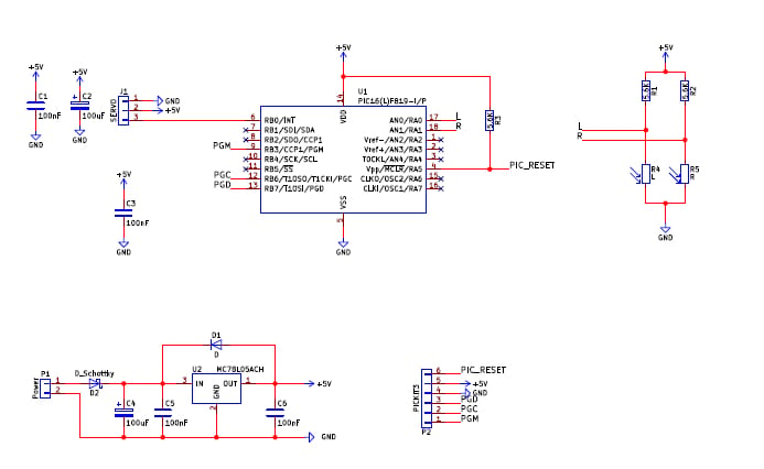
Schematic
How the Solar Panel Tracking System Works
The solar panel tracking system project has two main components:
- The circuit board
- The microcontroller firmware
The circuit itself is very trivial, with only a few parts: a servo connection, a microcontroller, two LDR sensors, and a simple power management circuit. The two LDRs are placed into tubes side by side, mounted onto the solar panel, and pointed in the same direction as the solar panels.
The functionality of the circuit is realized with the firmware on the PIC16F819, which handles the sensor readings and motor adjustments. When the PIC turns on, it starts by configuring the oscillator, configuring the IO ports, and setting up the ADC module so all of PORTA are analogue inputs with a left-justified result.
Once the initial configuration has been done, the PIC starts the main infinite loop. The first task for the microcontroller is to get readings from both sensors. This is done by correctly adjusting the ADC channel select, initiating the ADC to take a measurement, and then placing the result into the appropriate variable.
With both measurements taken, it’s time to determine which way to move the tracker. If the left sensor detects more light than the right sensor, then the unit needs to turn counterclockwise (toward the left). If the right sensor detects more light that the left sensor, then the unit needs to turn clockwise (toward the right). If both sensors are the same, then the unit is sitting in the optimum position. Once the requested angle has been adjusted, it needs to be sanitized, which is done with a range check (lower than 0 or greater than 60 are invalid angles for the TG9e servo). The last thing to do is to convert our angle to a time delay. This is done with convertAngle(), and this function returns a number that, when fed into delay(), will result in a time delay that the servo will respond to correctly.
With the angle conversion done, it’s time to turn the servo to the correct position. Servos work with pulse lengths varying between 1ms and 2ms. A pulse length of 1m is the smallest length and represents 0 degrees, whereas 2ms represents the maximum angle of rotation (for the servo I am using, it's 60 degrees). The first delay turns on the servo port for 1ms (the default), and the second delay keeps the port on for the angle position time (angleTimeConversion).
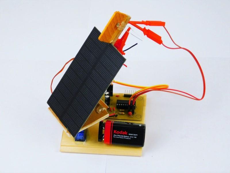
The circuit in this project can be constructed using many different techniques, including stripboard, breadboard, matrix board, and PCB. For this project, I have used a PCB, as they are easier to construct than wired circuits, and because I now use 7805 ICs in SOT-89 packages. The solar tracker itself can be built using many different mechanical kits, including Lego and Knex, but the servo used here has enough torque to allow the solar panels to be directly mounted to a panel, which is then mounted to the servo.
The solar tracker complete
Downloadable Files
Related Articles