Use this discreet bolt system to open and close just about anything only after a PIN entry on a keypad.
An easy way to control a lock bolt using a micro linear actuator is with a programmable membrane switch keypad. A simple access control system for cupboards, cabinets, refrigerators, and other doors is a user-friendly solution to keeping unwanted snoopers out and dangerous goods away from young curious fingers.
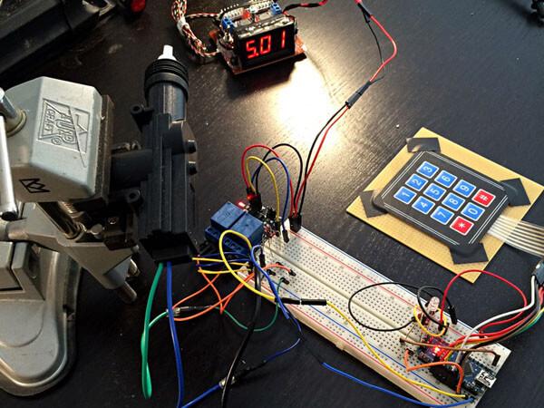
Using a 4x3 membrane switch keypad, an Arduino Nano microcontroller, and a small electric linear actuator to drive a discreet bolt system, anything that opens and closes can be set to do so only after a PIN entry on a keypad.
The keypad library is available from https://github.com/Chris--A/Keypad
Extract its contents, and put a folder named "Keypad" in your libraries folder. The contents of the Keypad-master.zip must be placed in that folder, do not extract it all into the libraries folder without creating the "Keypad" folder. If the Arduino program is open, close it and start it up again.
Wiring the System Together
First insert the Arduino Nano into the breadboard, making sure that the two rows of pins are on either side of the furrow in the middle.
TIP: Position the USB mini port so that it faces outward from the breadboard. This way it will not clutter up your wiring with a USB cable running through it.
The 4x3 keypad used in this tutorial has 7 female pin sockets, all of which need to be wired to the Arduino.
The keypad module uses 1, 2, 3, 4, for ROW0, ROW1, ROW2, ROW3, and pins 5, 6, 7 for COL0, COL1, COL2.
Wire it up as follows
Keypad > Arduino
- > ROW0
- > ROW1
- > ROW2
- > ROW3
Pins:
- > COL0
- > COL1
- > COL2
The following table may be useful, unless you prefer to use a multimeter (set it to <= 200 Ohm if it isn't the autorange kind). If you decide to find the connections yourself, first attach one probe to pin 1, the second to pin 2, then 3, etc. Next, attach one probe to pin 2, the second to pin 3, then 4, etc. While doing so, press all the buttons in sequence, 0, 1, 2, 3, 4, 5, 6, 7, 8, 9, '*', 0 and '#'. Eventually your table will be similar to this:
Keypad Mapping
| X1, Y1 = '1' | Pins 1 & 5 |
| X2, Y1 = '2' | Pins 1 & 6 |
| X3, Y1 = '3' | Pins 1 & 7 |
| X1, Y2 = '4' | Pins 2 & 5 |
| X2, Y2 = '5' | Pins 2 & 6 |
| X3, Y2 = '6' | Pins 2 & 7 |
| X1, Y3 = '7' | Pins 3 & 5 |
| X2, Y3 = '8' | Pins 3 & 6 |
| X3, Y3 = '9' | Pins 3 & 7 |
| X1, Y4 = '*' | Pins 4 & 5 |
| X2, Y4 = '0' | Pins 4 & 6 |
| X3, Y4 = '#' | Pins 4 & 7 |
X denotes COL(UMNS), Y denotes ROW(S), (sinus and cosinus values are inverted for convenience).
Pins range from 1 to 7, with the keypad's buttons facing toward you, left to right.
Wiring the Arduino Nano to the Keypad
- Arduino D5 -> keypad pin 1
- Arduino D4 -> keypad pin 2
- Arduino D3 -> keypad pin 3
- Arduino D2 -> keypad pin 4
- Arduino D8 -> keypad pin 5
- Arduino D7 -> keypad pin 6
- Arduino D6 -> keypad pin 7
Now it’s time to wire up the RGB LED. The only colors needed for display are: red and blue. From left to right (the LED has a flat side on its head) the pinout is RED, GND, GREEN and BLUE. Wire 5V to GND (Common anode) and set a 220 ohm resistor in series from pin 1 to D9 on your Arduino. Next, set a 220 ohm resistor in series from pin 4 to D8 on your Arduino.
Next, take the dual channel relay. On the relay terminals, there should be text something like 'NO1', 'COM1','NC1' etc.
- NO means Normal-open
- COM means Common
- NC means Normal-closed
Normal-open is the terminal port to insert a wire into if you want it to be ON when you activate that relay channel. When it is activated, you continue the circuit via the COM port, and from there to your micro linear actuator. NC is similar to NO, it just completes a connection when the relay is OFF instead of ON.
H-bridges and motor shields are typically reserved for super-fast operation, but since we only need to switch polarity based on a command or condition (ex. the correct pin code entered), the relay can function as an H-bridge.
Wire it up as follows:
- Arduino 5V to relay VCC pin
- Arduino GND to relay GND pin
- Arduino D7 to relay S1 pin across a 220 ohm resistor
- Arduino D6 to relay S2 pin across a 220 ohm resistor
- 12V GND to NO1
- 12V GND to NO2
- 12V VCC to NC1
- 12V VCC to NC2
- 12V VIN/VOUT from COM1/COM2, alternating, but never both ON or OFF simultaneously.
Once correctly wired up, you will have a simple way to safeguard your valuables or dangerous goods.
You can also customize the code to fit your own design and function requirements. For example, you could add a timeout, after which the actuator locks again.
To operate the keypad, hold "*" a short moment to enter PIN entry mode. The RGB LED will blink violet three times. Then you can enter your own custom PIN code. There should be one violet blink for each digit entered. When you have finished entering the PIN code, hold "#" a few seconds. The LED will blink blue if the entry is correct, or red if it is incorrect. If it is correct, your electric linear actuator will extend or retract, depending on its current state.
The PIN can be changed in the program's source code, which can be downloaded here: AccessControlKeypad