Create a digital kitchen timer, complete with a knob, buzzer, and digital display, using GreenPAK.
Learn how to create a digital kitchen timer, complete with a knob, buzzer, and digital display.
The system has two GreenPAK IC devices, one to keep time and the other to drive the display.
The schematic is shown in Figure 1. A button is configured to start, pause, continue, and reset the timer. A maximum of 1 hour (or 59 minutes) can be digitally stored.
The quadrature knob interface is derived from AN-1101 Unclocked Quadrature Decoder.
Storing the Time
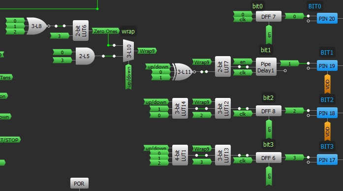
The time is stored in two sets of DFFs, one that represents the tens digit, and another for the ones digit. The DFFs count in binary from 0000 to 1001 (or 0 to 9 in decimal) for the ones digit and from 000 to 101 (or 0 to 5 in decimal) for the tens digit. The maximum storable value is 59.
The ones digit inputs are gated by a "Wrap" signal and an "Up/Down" signal. The Wrap signal indicates when the digits have reached 0 or 9, and forces the next value to wrap around to 9 or 0, depending on the counting direction. For the tens digit, the wrap occurs when the digits have reached 0 or 5 and forces the next value to be 5 or 0. The Up/Down signal signifies the counting direction, which comes from the Quadrature Decoder.
The tens digits has an overflow input. When a wrap occurs in the ones digit, the tens digit must count to the next value.
Figure 1. 1s digit counter (Matrix 0)
Figure 2. 10s digit counter (Matrix 1)
Quadrature Decoder
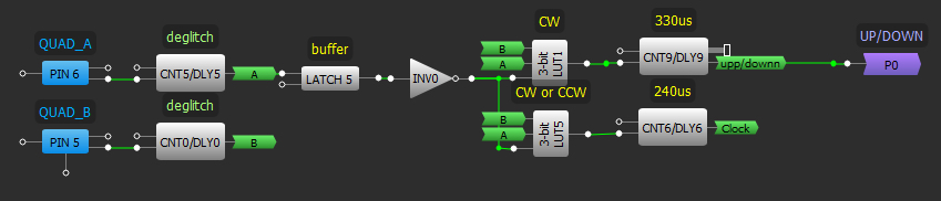
The quadrature knob is a 3-pin device where two outputs A and B are pulled up to the supply, and the third pin to GND. These two outputs A and B will pulse low sequentially, depending on the direction the knob is turning. For clockwise, A will go low first, followed by B, and for counterclockwise, B will go low first, followed by A. Based on this information, we can detect what direction the knob is turning.
This design is a variant of AN-1101 Unclocked Quadrature Decoder and includes a deglitch filter to eliminate contact bounce. The decoder outputs a short pulse that occurs at each CW rotation (3-bit LUT1) and either a CW or CCW rotation (3-bit LUT5). A clockwise rotation will cause a 330us one-shot on Up/Down, while both a clockwise and counterclockwise rotation will cause a 240us one-shot on Clock. The difference in length allows DFF inputs to settle.
Figure 3. Quadrature Decoder
Figure 4. CW (3-bit LUT1) and CW or CCW (3-bit LUT5) Properties
Button Logic
The BUTTON PIN#10 input starts, pauses, continues, and resets the timer. The device initializes to the "Pause" state, where the timer can be set. By pressing BUTTON, the state will toggle between Pause and Start. In the Start state, the Up/Down signal is forced low and the 1-minute counter CNT2/DLY2 begins. Toggling the Pause/Start DFF can pause and continue the timer.
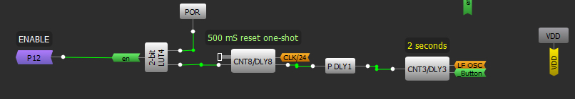
To reset the timer, hold the button for 2 seconds. A one-shot resets all timer DFFs and resets the state of the device to Pause (see Figures 5 and 6).
Figure 5. Button and Pause/Start DFF
Figure 6. 5 second triggered 500mS Reset One-Shot
Buzzer Timeout
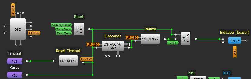
When the timer reaches zero, the device enters a Reset Timeout where the buzzer output is enabled and the counter stops at zero. The buzzer will buzz once every 3 seconds for 250ms. During the 250ms, the buzzer is driven rail-to-rail at 3.125kHz. After the timeout, the Pause/Start DFF is reset to the Pause state (See Figure 6). Alternately, the user can manually toggle the DFF, which will end the Reset Timeout.
Figure 7. Buzzer and Reset Timeout
Kitchen Timer LED Driver
A second GreenPAK IC contains enough internal circuitry to implement and drive a 2-digit, 7-segment display.
Figure 8. LTD-4708JF display
Figure 9. LTD-4708JF Pin Connection
The 7-segment displays with common cathode are connected to the 2-chip, kitchen timer + display driver GreenPAKs as shown in the figure below.
Figure 11. GreenPAK Design
The timer chip counts to 59 minutes, thus the first digit can be any from 0 to 5, and the second digit any of 0 to 9. The display chip will know which output — bit or (10s) BIT) — is coming to the display inputs based on select pins: output pin 12, connected to pin 4 of the display; and pin 13, connected to pin 9 of display. As shown on figure 2, for LTD-4708JF, display Pin 4/Pin 9 is common cathode for Digit 1/Digit 2, which must be low to activate. The driver activates first one digit, then the other, with the frequency around 1.02 kHz so the eye cannot see the blinking.
Pin 2/DP pin of the display is for the dot and it is connected to ground — it is always inactive.
Conclusion
We created a fully functional kitchen timer, with start/pause/reset features, buzzer output, and 7-segment driver. The maximum storable value is 59, because we are limited by the number of resettable DFFs. Suggested improvements include adding an indicator LED to represent the different modes, as well as optimizing the design to fit into smaller GPAK devices, which will lower the cost and board space.
Downloadable Files
Related Articles