This object counter uses an IR beam that, when broken, increments a counter.
A circuit that counts how many people walk through a door or how many times an object has passed a point can be very important. In this Maker Pro project, we will build an object counter that uses an IR beam, which, when broken, increments a counter.
How Does the Digital IR Counter Work?
The IR counter starts with the IR LED D2, which emits a beam of IR light. This beam is aimed onto the IR photodiode, which, in turn, increases the conductivity of the IR diode. Therefore, when the beam hits the IR photodiode in this circuit, the voltage across R2 increases. When the beam is cut, this voltage drops as the conductivity of the IR photodiode decreases. The potentiometer RV1 is set so that, when the beam is un-cut, the output of the op-amp IC1 is on, and when the beam is cut (i.e., blocked), the output of IC1 is off.
This output is then connected to the 4040 CMOS ripple counter, which counts on the falling edge of the input clock signal. Therefore, when the beam is cut, the counter increments by one. The reset input on the 4040 is connected to a tactile switch and pull-down resistor, such that when the button is pressed, the reset pin is connected to 5V and therefore resets the current count value.
The last part of the circuit is connected to a 7-segment display, which outputs the current count value. The IC that converts the binary value to hexadecimal is the HSEG1000, a segment driver IC that can drive up to two segments and output an 8-bit hexadecimal value. The HSEG1000 is used because most (if not all) seven-segment drivers do not output hexadecimal, and when values above 9 are placed on the input, the output remains blanks. The HSEG1000, however, displays the letters A–F for values above 9. The HSEG1000 can be found here (www.mitchelectronics.co.uk). The HSEG1000 IC in this circuit is configured in transparent mode by connecting MODE to 5V, WR to 5V, and the RESET input to 5V.
Construction
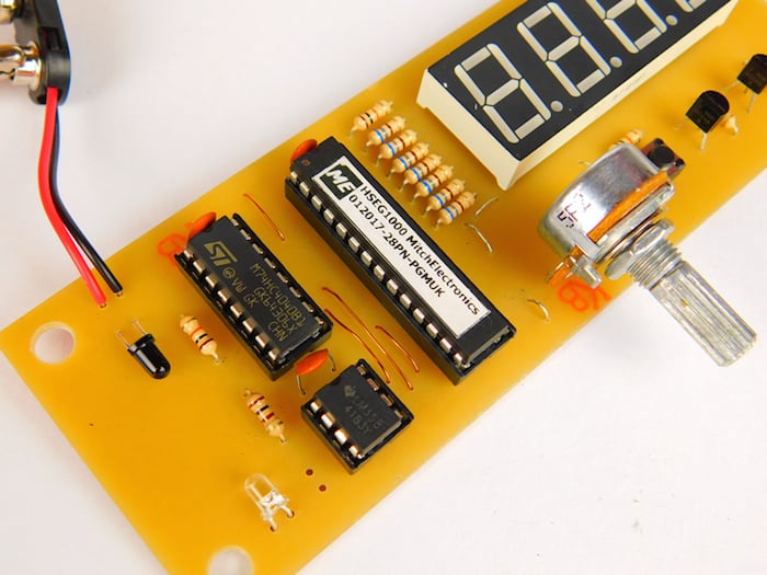
The IR counter shown here is constructed on a custom PCB made on a CNC milling machine (g-code files are attached in the project zip file). Of course, all parts (including the HSEG1000) are in through-hole form, which means this circuit could also be built on stripboard or solderless breadboard. While the IR diodes shown here are mounted on the PCB itself, they can be placed on a doorway or door, with wires connecting to the main circuit to record beam cuts. The trick to getting a reliable count is the potentiometer RV1. This potentiometer will need to be carefully configured so that the high and low values from the IR photodiode cross the voltage value generated from RV1.