Save money by making your own MIDI sequencer for creating and recording music.
Creating and recording music on computers is a hugely popular method for modern music creation. Unfortunately, music equipment is incredibly expensive. Even the most basic MIDI sequencer can set you back $100 easily.
In this DIY Hacking project, we will look at how to build a MIDI sequencer that won’t break the bank!
How Does the MIDI Sequencer Work?
Circuit Hardware
Can we really build a MIDI sequencer at home? The answer is yes and, when you see how simple they can be, you will never look at shop-bought MIDI mixer in the same way!
Before we build, however, we'll need to understand how MIDI sequencers work.
MIDI stands for Music Instrument Digital Interface and is, at its heart, a UART bus with a baud rate of 31250. While this baud rate may seem strange, it turns out that it is perfectly divisible into 8MHz which was a commonly used crystal in the past (MIDI goes as far back as 1980).
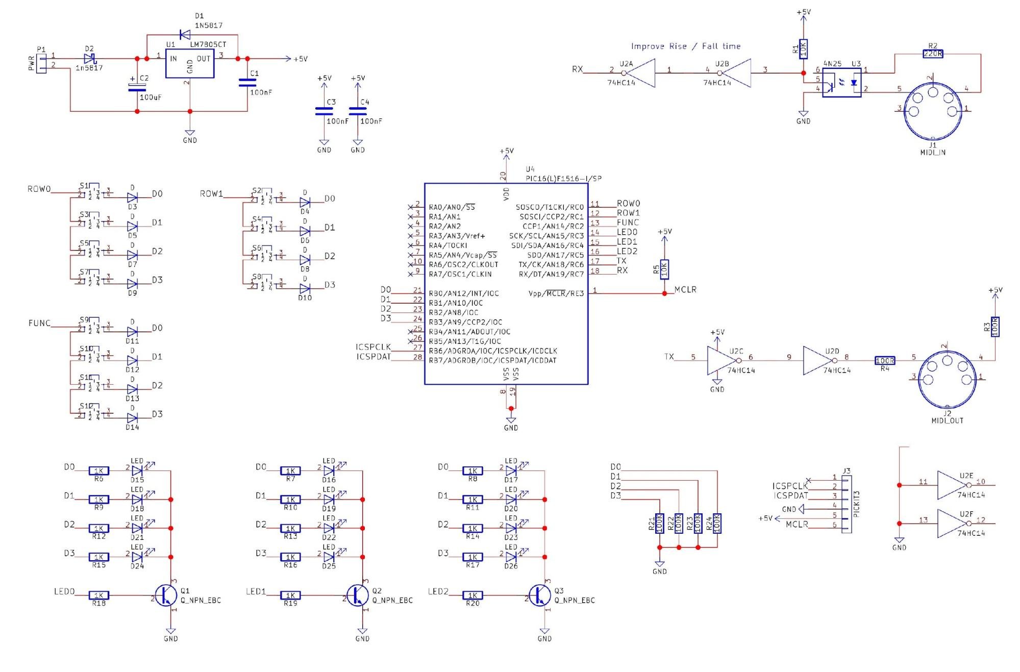
But MIDI is more than just a UART baud rate; it also includes a bit of circuitry and software, too! MIDI connections are (or at least should be) optoisolated and so our MIDI output uses two series resistors with an inverter (for driving), while our MIDI input uses an optoisolator and a Schmitt trigger buffer. The buffer, itself, is made of two inverters (to cancel out the inverting effect), while the Schmitt trigger action is used to improve the rise and fall times of the incoming UART.
The sequencer shown in this project has eight step buttons (pattern), four functional buttons, eight step LEDs, and four function LEDs. Since there are not too many IO pins on the PIC16F1516, row selection is being used, which means that each row is enabled and scanned to see which buttons have been pressed. (See my project, the DIY Laser Tripwire, to learn more.)LEDs are also turned on in waves very quickly (faster than the human eye can see) so all the LEDs appear to be on at the same time.
The only other circuit is the LM7805 linear regulator that uses the same standard circuit found in most of my projects.
PIC Software
The software in this project is the brains and is what turns a simple microcontroller and a few buttons into a fully-working MIDI sequencer. While the code for this project is rather large and would take too long to explain, the key points will be covered! MIDI uses a basic packet system which involves a command and then some associated data bytes. The commands in MIDI are one byte in size with the specific command being the four most significant bits while the channel is the lower four bits. The channel is very important as this is the “port” that your instrument communicates through. Since the channel choice is four bits long, the total number of channels on one MIDI line is 16. In our project, we use channel 0.
The MIDI Command Structure
| B7 |
B6 |
B5 |
B4 |
B3 |
B2 |
B1 |
B0 |
| a |
a |
a |
a |
C |
C |
C |
C |
- Note On (aaaa = 1001)
- Note Off (aaaa = 1000)
- Polypress (aaaa = 1010)
- Control Change (aaaa = 1011)
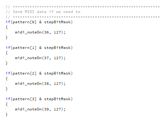
Once the command byte has been sent, data bytes may need to be sent (depending on the command). In our project, we only use one command, Note On, and this has two associated bytes. The first byte is the note that has been pressed and the second byte is the velocity of this note (essentially the volume).
To make things easy, included in this project is a basic midiCommands.h file that includes a Note On and Note Off function that only requires you to pass the note and volume. However, you must call midi_setChannel(unsigned char channel) to set the channel that you want to use.
In our project, I used 0x09 (I have other music equipment) but this number has to be between 0x00 and 0x0F (remember, we have 16 channels).
You can read more on MIDI here:
Our simple sequencer does not produce its own clock system and is synchronized by an external MIDI station (such as FLStudio). Therefore, if this project is not connected to a clock source it will sit idle. While this may sound strange, it is actually beneficial as the sequencer stays synced to the music software. This is done with a simple UART receive interrupt (as the master sends a time pulse message to the controller over the MIDI connection). When a message is received, the PIC increments a counter and when the counter reaches a certain value (depending on your MIDI clock), it will increment the sequencer.
When the step sequencer steps, it looks at the step sequence array (which holds the pattern for each instrument such as kick drum, hi-hat, and snare) and if any of the instruments need to be played then the PIC sends out the MIDI message to turn on the note (whose note is specific to the pattern).
The LEDs are event-driven (using timer2) for two reasons. Firstly, the LEDs are somewhat important (so you can see what you have entered in). Secondly, the interrupt system can be turned off and on (by the main code during button scans). The LEDs are not very bright in this project due to the very short period they are on for but this helps to free up as much processing time for UART message sending.
The buttons are scanned row by row (three rows of four buttons) and, depending on their state, function bits and step bits are adjusted. The sequencer includes four function buttons (only three of which are used) and their functions are next step pattern, back to pattern 0, and led mode.
Since there is no Schmitt trigger action on the port and the switches bounce, some vital debouncing code is included in the scanning code which uses a cooldown counter and the previous button state.
When a button is pressed, it will perform its action. If the button is held, it is ignored and as soon as it is released it starts a cooldown counter. While the counter is counting down, all button presses are ignored—only when the countdown value reaches 0 will further button presses be acknowledged.
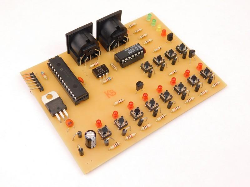
Construction
This project can be built using many different circuit construction techniques including stripboard, matrix board, breadboard, and even PCBs. I have used a PCB and some underwire routing to make this project. Because of some PCB errors, a PCB file is not being included in this project (too complex to explain how specific via connect).
This project is better suited for a double-sided PCB but a single-sided project is not impossible (as shown here).
Watch the MIDI Sequencer in action below:
For those who are interested, I no longer recommend making PCBs using a CNC machine and am personally switching back to a chemical process. Machining PCBs on a CNC results in poor trace quality where traces become weak as the neighboring material has been removed. My new PCB facility will include many neat features that will be demonstrated in future DIY Hacking projects.