Step-by-Step guide on how Lithium Battery charger circuit works and full assitance for DIY protect charger through USB port.
This step-by-step guidance and fully documented article will certainly help you to develop your own Lithium Battery charging circuit with a protective charging output.
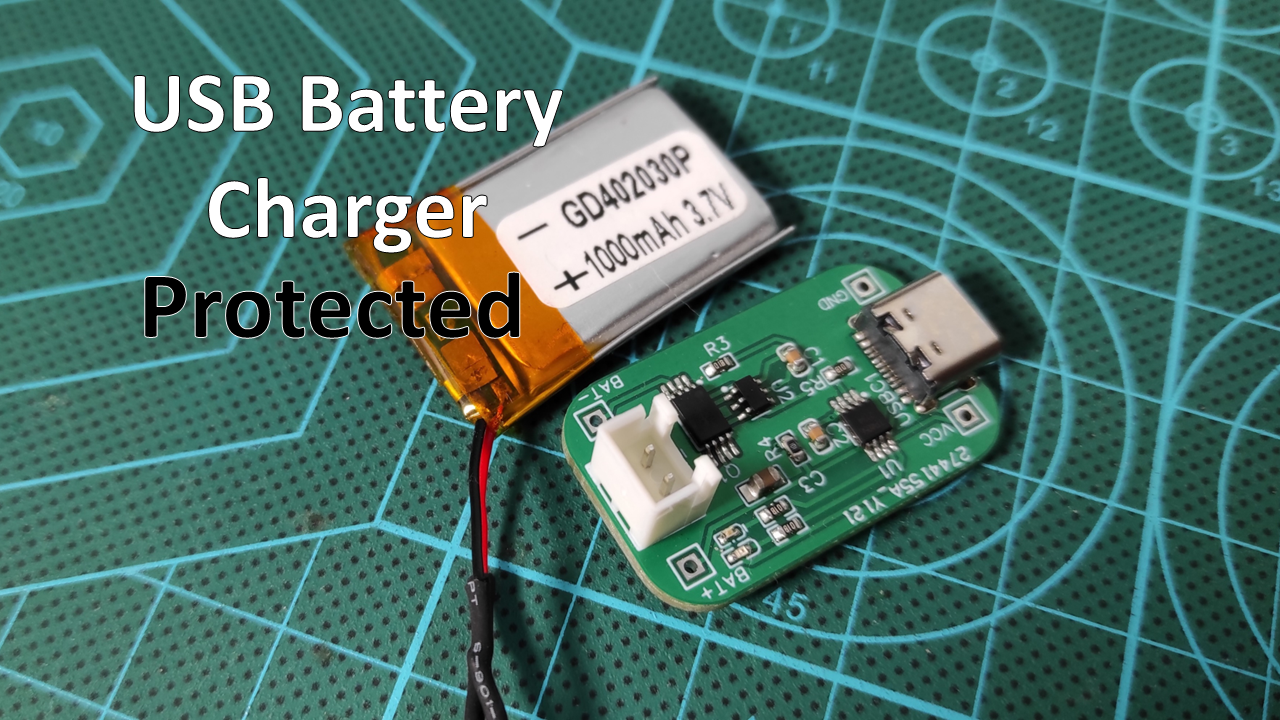
The Circuit has been designed around the TP4056 chip and some other Integrated Circuits for Battery protection.
You can buy this same circuit form several existing webstores but I preferred to Do It myself and this way I can integrate the charging stage in my wearable devices by copy-paste the circuit schematic so you can do the same.
The tools is up to you to define based on your skills, You can assemble the circuit using only a solder iron and solder core if you have some assembly skills but here I share the tools that I used easily complete the assembly of the Surface Mounted Parts, you may find that some tools are extra but you consider that it depends on your capabilities.
- I used a low temperature profile solder paste from CHIPQUIK SMDLTLFP10T5
- I used precision tweezers to deal with the small components.
- The small size hot plate MHM30 from miniware is suitable for the size of my circuit and I used (optional) a digital microscope camera to inspect the assembly results.
The Circuit Schematic
The Circuit Design
Charger Ciruuit Assembly
I put the solder paste on the components exposed pads, and placed the components to their placements on the board, I used precision tweezers for this task because I'm dealing with very small components here.
The next step is soldering, I'm very happy to use the cool small size soldering hot plate from miniware, especially because it matches the small size of my PCB designs.
I shared a microscopic view of the soldering process.
Do not forget to clean the board with some flux removal solvent,
I then added the Battery header connector and soldered the through hole pins of USB connector.
Test the Circuit
As I mentioned in the beginning of this article, this same circuit is available in several electronics webstores, but I just Did it myself to test its functioning and now this confirmed circuit schematic is useful for my future designs and I can directly include it to the coming gadgets.
We could make this circuit provide charging for Battery and power the load circuit at the same time by placing a PMOSFET at the power main line entry of the load so this will disconnect the load from the Battery OUTPUT while charging which allows the TP4056 to sense the charging level without any perturbation from the load.
Let me know your thoughts in the comments section.