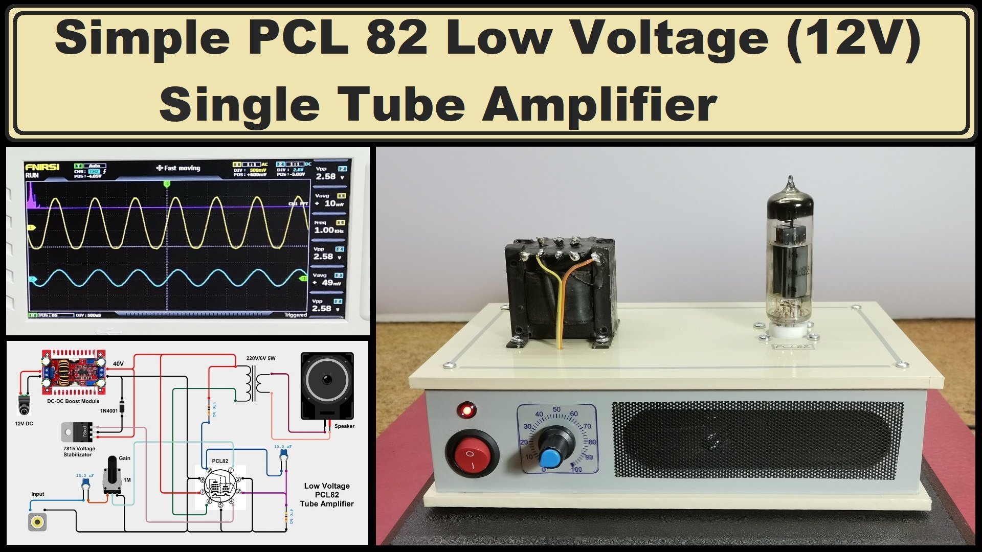
How to make a very simple single tube amplifier that also works at low voltage and is powered by 12V DC. Also, instead of an output audio transformer, a standard 220V/6V mains transformer is used.
A valve amplifier or tube amplifier is a type of electronic device that uses vacuum tubes to increase the amplitude or power of a audio signal. Until the invention of the transistor, all electronic amplification was produced by valve (tube) amplifiers. Nowadays, this amplifiers are again popular among audiophiles, and their price is usually very high.
Valve amplifiers produce greater amounts of total harmonic distortion, but this type of distortion (2nd harmonic) is not as disturbing to the ear, and is perceived as a "warm" pleasant sound, especially when playing instruments where this amplifiers are still indispensable. This type of amplifiers are not very popular with DIYers mostly because they use high voltages (more than 200V) which are usually difficult to perform and are very dangerous. This time I will describe to you how to make a very simple single tube amplifier that also works at low voltage and is powered by 12V DC.
As we can see in the schematic diagram, the device consists of several parts, which I will describe individually.
The power supply part consists of a 12V source of DC voltage, which is then increased to 40V through the DC-DC Boost Module, which is needed to power the Tube anode. The heating voltage of this lamp is 16V/300mA and is obtained at the output of the 7815 Voltage Stabilizer using the diode. An interesting option is if we have 16V at the input of the Boost module, in which case we can use this input voltage directly for heating, leaving out the stabilizer. Of course, instead of the Boost module, you can use a transformer with a 40V DC output (after rectifier) plus a 16V AC output for heating. I used the described power supply because I had the boost module at the time of construction.
If you want to make a PCB for this project, or for any other electronic project, PCBway is a great choice for you. PCBway is one of the most experienced PCB manufacturing company in China in field of PCB prototype and fabrication. They have a large online community where you can find a Open Source projects, and you can also share your project there. From my personal experience I can tell you that on this community you can find many useful projects with alredy designed PCBs, from where you can place an order directly.
The input section consisting of a capacitor and a potentiometer with a value of 1 Megaohm, with which is adjusted the Gain of the amplifier. This part is the heart of the amplifier, the PCL82 tube which consists of a triode and a pentode, plus two resistors and a capacitor. Instead of PCL82, without any change in the schematic, ECL82 can be used, in which case the heating voltage should be 6.3 volts.
And finally, the output part, which consists of an audio transformer taken out of an old tube radio, or, as in my case, a 220V/6V mains transformer with a power of about 5 Watts, whose secondary part is connected to a speaker.
The amplifier is located on this top panel on which the tube and the audio transformer are mounted, and the rest of the parts are located in the box. The boost module, the potentiometer, and the speaker are integral parts of the amplifier, and on aluminum cooler there are voltage stabilizers that generate several different voltages that in the future I plan to use to power other external devices.
While testing, as a signal source I will use the Line Out output from the computer. With no input signal present, with the potentiometer in the far right position, no noise or hum is heard, which is a sign of a well-conducted ground and a well-filtered supply voltage. Of course, you'll have to trust me about the sound quality because you'll hardly be able to notice it on a YouTube video. The output power is about one watt without unpleasant audible distortions, which is quite sufficient for the purpose for which I built it. Namely, I will use this amplifier in my next simple radio projects as an audio output part. However, with high-sensitivity speakers with a light membrane with a large surface area, this power is quite sufficient for normal listening.
Let's trace the output signal on an oscilloscope, when a sinusoidal signal from a tone generator is brought to the input. For this purpose, I will use multifunctional device, which is basically a two-channel oscilloscope, but also has a Signal generator with a frequency of up to 7 MHz. This oscilloscope is also an option for FFT Spectral Analysis of the signal. Otherwise, the purpose of this instrument is not to measure distortions and signal strength, but we can determine these characteristics approximately by visual inspection of the output signal. At the input of the amplifier we bring a sinusoidal signal with a frequency of 1 kilohertz, the shape of which is represented by blue color, and the output signal is yellow. The spectrum analysis is in purple. Now we amplify the output signal until we notice certain distortions of the yellow sinusoid. We notice that the amplitude of the signal is about 2Vpp when the sunusoid starts to distort. Since we know that the resistance of the speaker used is 4 Ohms, according to Ohm's Law, the output power is about 1 Watt with minimal distorsions.
The device is built into a suitable box made of 5mm PVC board and lined with self-adhesive wallpaper, and it also serves as a speaker box.