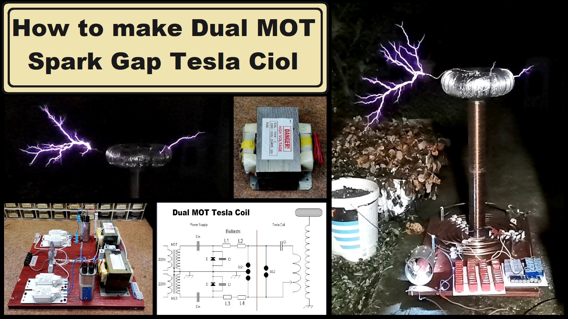
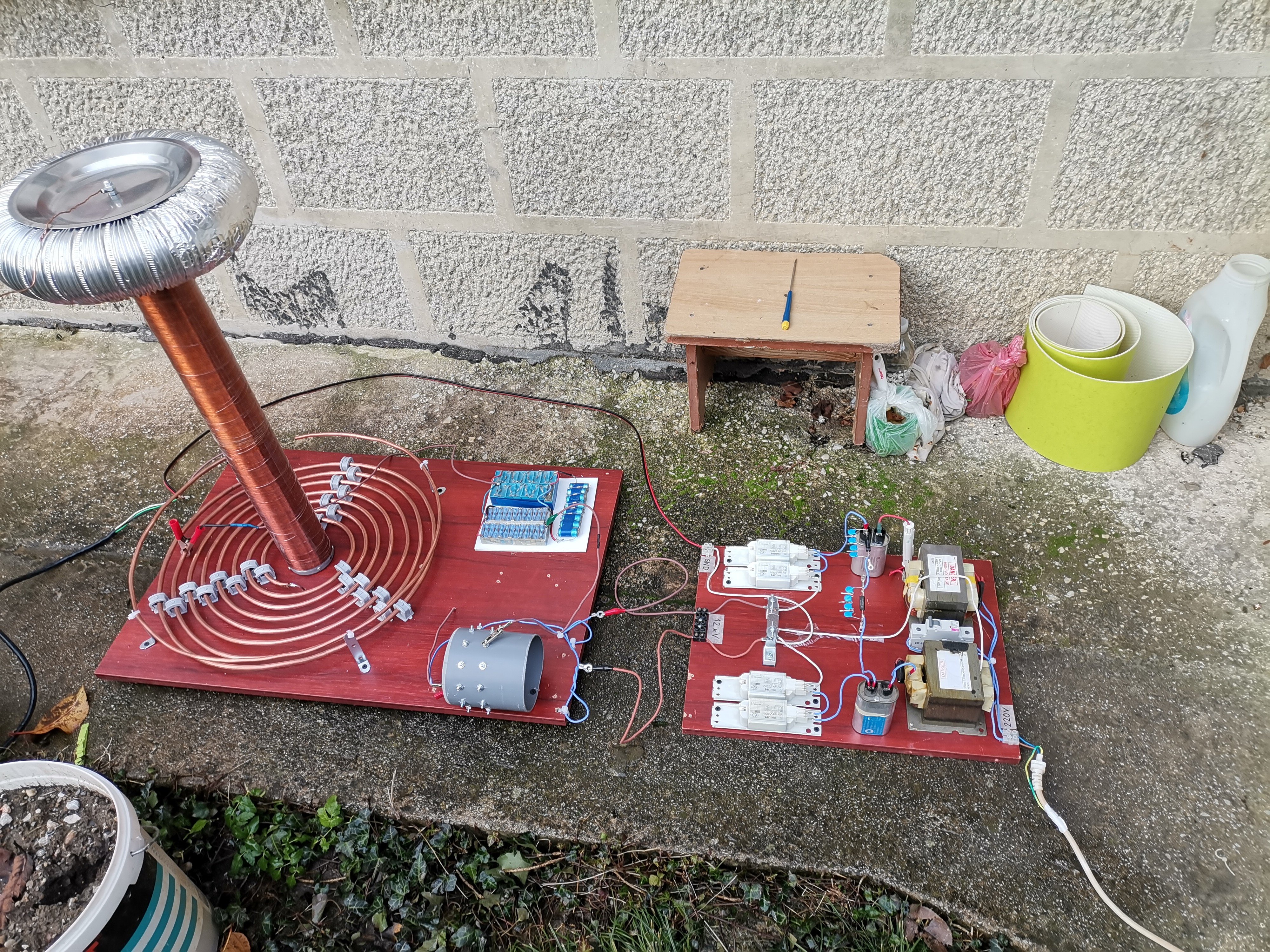
Alternatives to the Neon Sign transformers are microwave oven transformers (MOT), because they are universally available for free, or at very low cost from broken microwave ovens. This is a Spark Gap Tesla Coil made with two MOTs.
Tesla coils are known for their ability to generate visually impressive electrical arcs or sparks, making them popular for educational demonstrations, entertainment, and as a hobbyist project. However, more "exotic" parts are required for its construction, among which the HV Transformer is the most difficult to obtain. An old Neon Sign Transformer is often used, but they are difficult to locate in many countries. Likewise, new NSTs are prohibitively expensive for the hobbyist. Alternatives to the neon sign transformers are microwave oven transformers (MOT), because they are universally available for free, or at very low cost from broken microwave ovens.
However, the voltage of their secondary is not sufficient to drive the Spark Gap Tesla Coil. The simplest way to achieve it is to use more than one MOT. Another option is to use some sort of voltage multiplying circuit. It is most practical to use both options, two transformers plus a multiplayer, which is described in this project. In one of my previous videos I described how to make a simplest Spark Gap Tesla coil using an NST transformer. This time I will use the same components from that project, except the high voltage source.
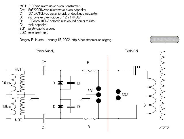
And now let's explain how this type of high voltage source works and is made. I first built it according to Greg's Garage Tesla Coil Site where this schematic is presented, but the multiplayer didn't work.
This project is sponsored by PCBWay. They has all the services you need to create your project at the best price, whether is a scool project, or complex professional project. On PCBWay you can share your experiences, or get inspiration for your next project. They also provide completed Surface mount SMT PCB assemblY service at a best price, and ISO9001 quality control. Visit pcbway.com for more services.
At the very beginning, the part with the diodes connected in series was not clear to me, so I decided to look at the circuit of the simplest so-called Willard half-nave voltage doubler. In our case, we have two such doublers, so analogously to that, it would be logical for the circuit to look like this, that is, the grounding should be connected between the two diodes.
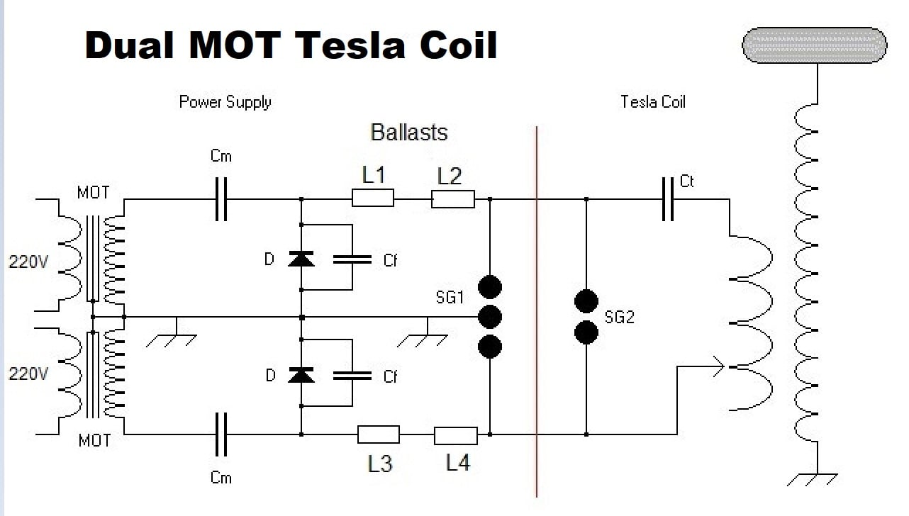
This is the final circuit based on which I built the device.
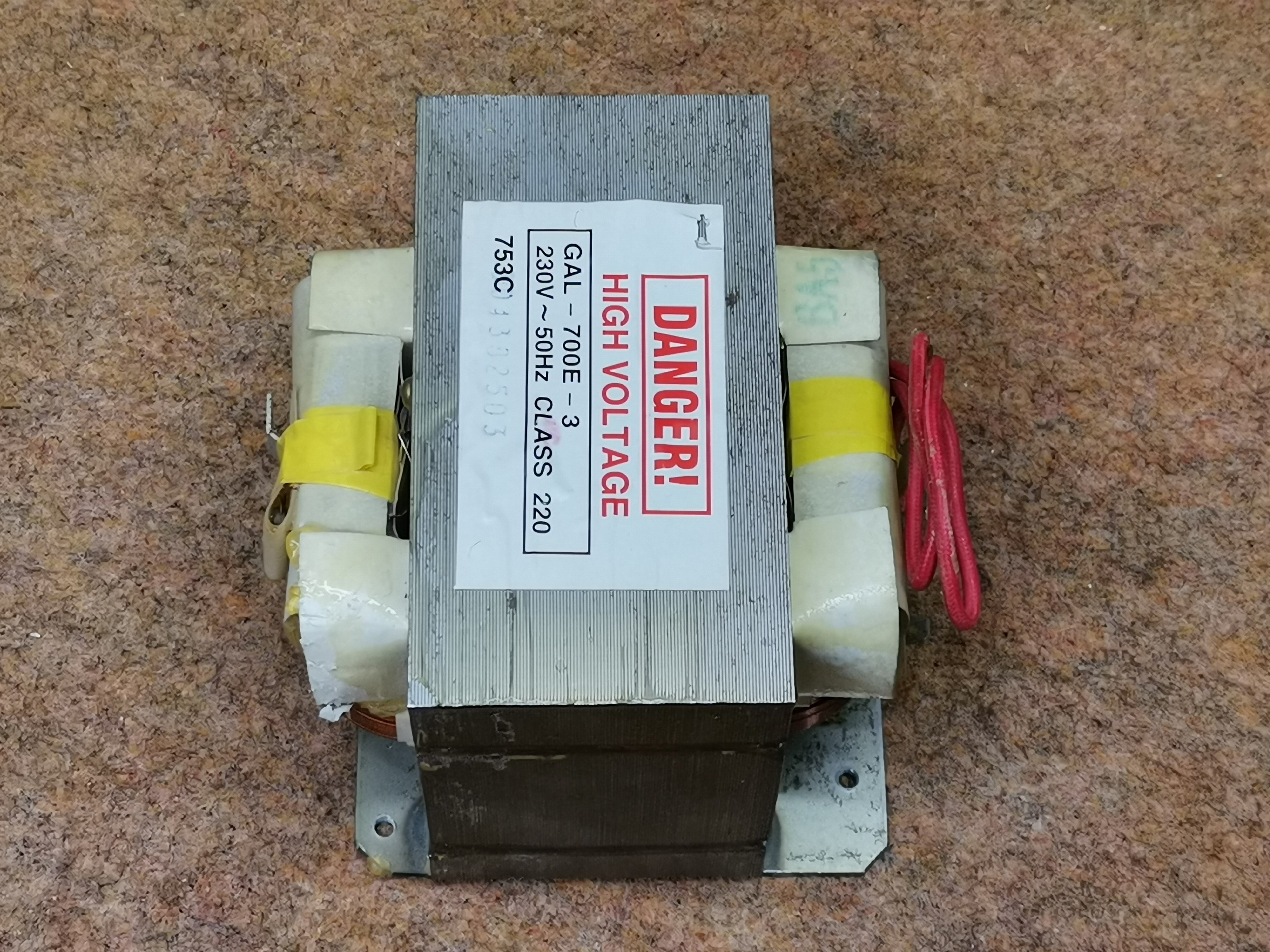
Basically for the sake of economy I decided to use as many parts as possible from an old microwave oven. In this case, these are transformers, capacitors, and diodes. The primary windings are in parallel connection, and through a suitable fuse are connected to the mains supply. The secondary windings are in series to produce twice the voltage. Let me mention that at MOT one lead of the secondary is always connected to the core of the transformer, in order to avoid the use of expensive insulating material. So the cores are connected to each other, and to the grounding of the device. Capacitors are connected to the other ends, and two diodes are connected in series to them, the middle of which is connected to ground.
In Greg's Scheme, two 100 Ohm 100 Watt resistors and 1nF 10kV capacitors are used in parallel with the diodes that form an RC low-pass filter intended to attenuate any RF feedback from the Tesla coil. These feedback signals can momentarily damage the high voltage diodes. Unfortunately, resistors with such high power are very difficult to obtain, so I successfully use four ballasts from fluorescent tubes instead them wich are actually chokes.
In the following, there is a symmetrical safety gap where the grounding is in the middle, which serves to protect MOTs. With this, the power supply part is ready and we can connect it to the rest of the components of the Tesla Transformer. I will not explain the function of the other components in detail this time, because it is described in the video mentioned above. Now the NST will be replaced by the device described so far. Since the Dual MOT transformer provides a relatively higher current of several hundred milliamps, the capacitor bank should also have a higher value.
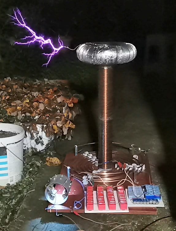
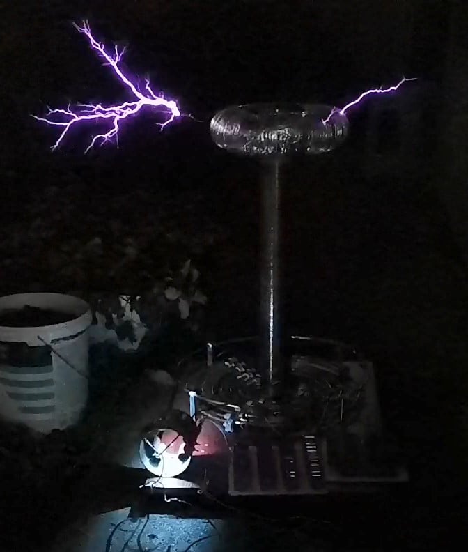
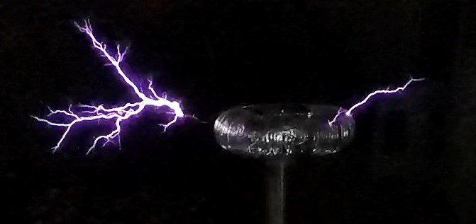
Next, let's look at how this Tesla transformer behaves in real conditions:
As you can see in the video, with these components and a short tuning I was able to achieve a spark length of more than 50cm. The fluorescent lamp is lit at a distance from the transformer of 2.5m and more. During the first shots, as a precaution, I did not let the transformer work continuously for more than 20 seconds. Then I tested it with continuous operation for 1 minute and more, so the diodes were completely cold. I only had a problem with excessive heating of the spark gap due to the higher value of the current.
And finally a short conclusion. I am very pleased with the results of this Tesla Coil, although I think with further tuning they would be much better. Especially with increasing the capacitor bank, but unfortunately at the moment I used all the capacitors I had available. I expect a shipment of capacitors to arrive soon, so if there are new results, I will present them to you in one of the following videos.
SAFETY NOTE: Please do not attempt to recreate the experiments shown on this video unless you are familiar with High Voltage Safety Techniques! Direct Current even above 60V maybe lethal, even when the AC supply voltage has been disconnected due to the stored energy in the capacitors. I have no responsibility on any hazards caused by the circuit. Be very careful. This is a humble request.