This project demonstrates various ways to
output data serially from the GreenPAK devices.
This project demonstrates various ways to output data serially from the GreenPAK devices.
We will cover GreenPAK4 and GreenPAK5 devices but some of these techniques can apply to older PAKs as well. First, serial data is a pattern of logical 1s and 0s used to communicate with another device, such as an MCU, that will interpret the 1s and 0s for its own use. The data could represent device ID, serialized parallel data, or an arbitrary pattern. This app note explains the six basic serial output techniques using GreenPAK components from the simple pattern generator to the more complex 8-state state machine.
To follow along, please download the GP files Serial_Output_Techniques_PAK4, Serial_Output_Techniques_PAK5_Horizontal and Serial_Output_Techniques_PAK5_Vertical. The first file contains general techniques and the latter two contain state machine examples.
The design was created in free GUI-based GreenPAK™ Designer software.
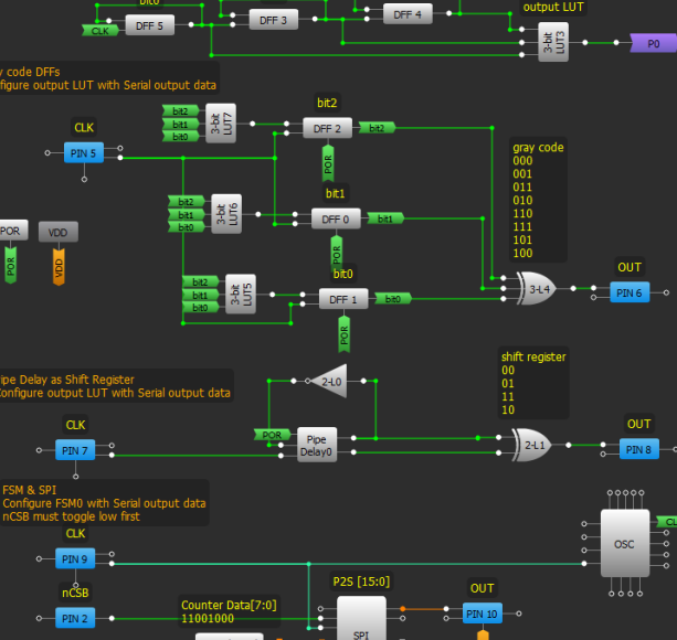
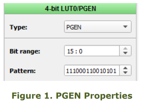
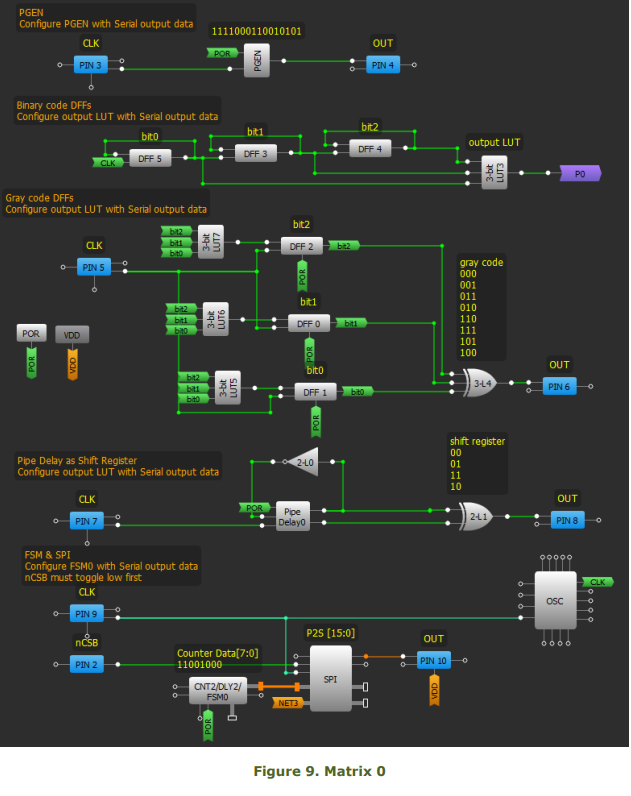
PGEN
The simplest to understand, the PGEN is already designed to be a pattern generator. Each rising edge of CLK shifts out the next bit in the pattern and wraps around.
• Make matrix connections as shown in Figure 9.
• Configure Pattern with the desired serial data. (max. 16-bis)
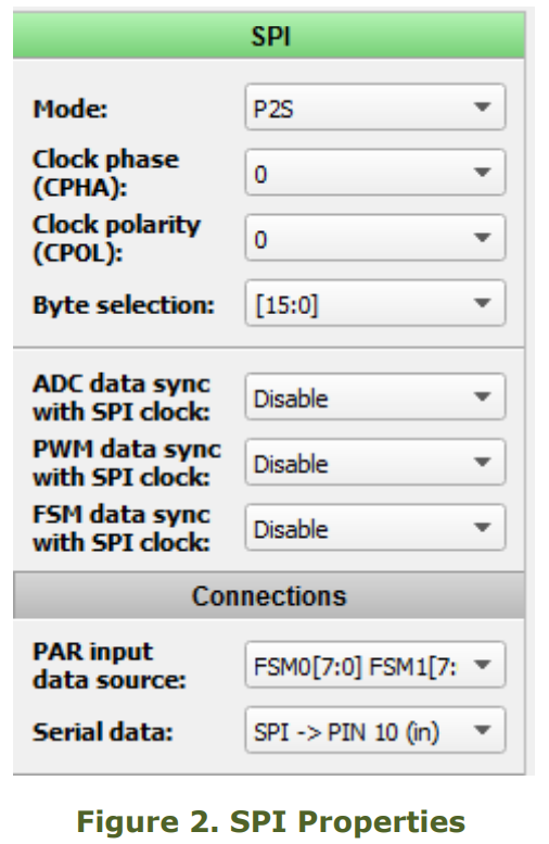
FSM and SPI
This example is written in another app note, AN1083. FSM counter data is converted to serial data via the SPI block. The output pin is preset to PIN12 for SLG46620V. To start-up the SPI, the nCSB input needs a high to low transition. For a detailed explanation, read AN-1083 SPI Parallel to Serial Converter.
• Make matrix connections as shown in Figure 9.
• Set SPI to ‘P2S’ mode
• Set Byte Selection to [15:0] or [7:0]
• Set PAR input data source to ‘FSM0[7:0] FSM1[7:0]’
• Configure Counter Data with the desired pattern.
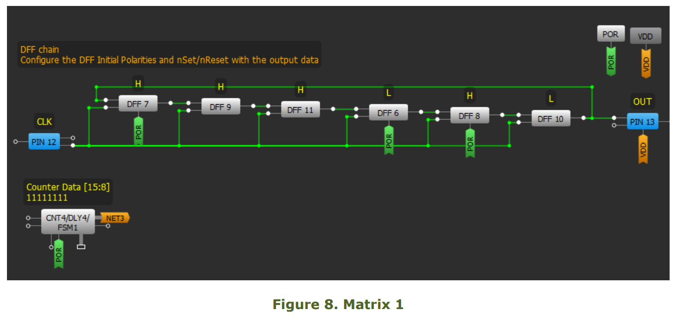
DFF chain
A pattern is stored in D Flip Flops where each DFF stores one bit. By connecting DFFs in a register string, data is clocked out serially. The number of DFFs is linearly proportional to the number of bits in the pattern.
• Make matrix connections as shown in Figure 8.
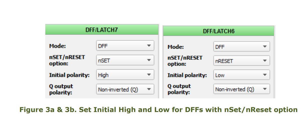
• Connect the nSET/nRESET input to POR where applicable.
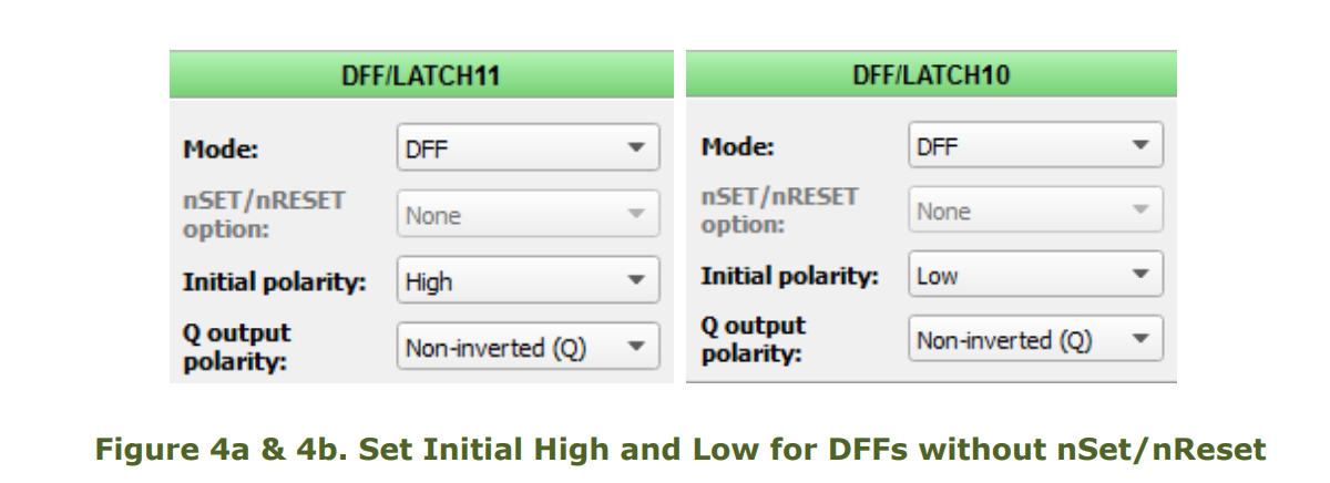
Configure the initial polarity and nSET/nRESET of each DFF with the corresponding bit in the data. Follow Figures 3a, 3b, 4a, and 4b.
The number of DFFs used is exponentially proportional to the number of bits in the pattern (power of 2). The only caveat is the propagation glitches between state transitions. This happens because transitions are level sensitive and binary code could change multiple bits simultaneously.
To avoid glitches, the output should be synced to the falling edge of clock, or filtered.
• Make matrix connections as shown in Figure 9.
• Connect the nSET/nRESET input to POR where applicable.
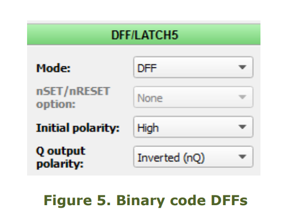
• Configure the initial polarity to High, and Q output polarity to Inverted(nQ)
• Configure the OUT of the Look-Up-Table with the desired pattern in the order of binary states from 000... to…111.
Gray code DFFs
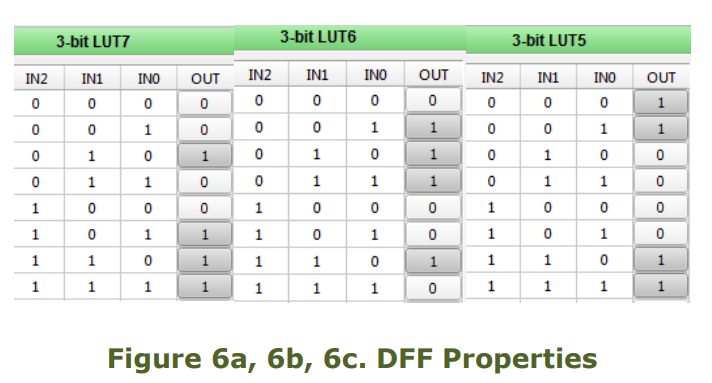
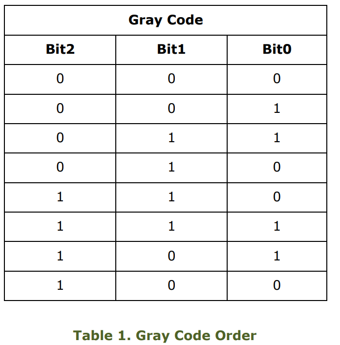
Similar to the previous example, this one uses gray code as the state transitioning order {000, 001, 011, 010, 110, 111, 101, 100}, which avoids transitional glitches. We will need three sets of 3-bit LUT and DFF, one for each bit and one 3-bit LUT to configure the output pattern. The number of DFFs and LUTs used is exponentially proportional to the number of bits in the pattern (power of 2). Patterns requiring more than 8
states are highly inefficient in gray code because
it uses too many circuit resources.
• Make matrix connections as shown in
Figure 8.
• Connect the nSET/nRESET input to POR
where applicable.
• Configure the OUT of the 3-bit Look-UpTable with the desired pattern in the order of gray
code states from 000... to…100.
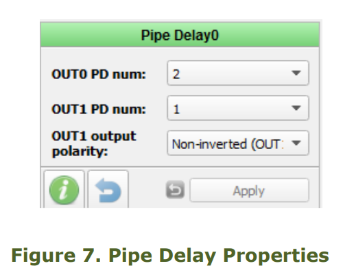
The Pipe Delay is a bunch of DFFs with three outputs. We can use it as a shift register and toggle the input such that we cycle through the states {00, 01, 11 and 10}. A 3-bit shift register states would look like {000, 001, 011, 111, 110, 100}. Using a shift register for the state machine also avoids transitional glitches like gray code, but the number of bits needed is linearly proportional to the number of bits in the pattern (2x).
• Make matrix connections as shown in Figure 9.
• Configure the OUT of the 2-bit Look-UpTable with the desired pattern in the order of shift register states 00… to… 10.
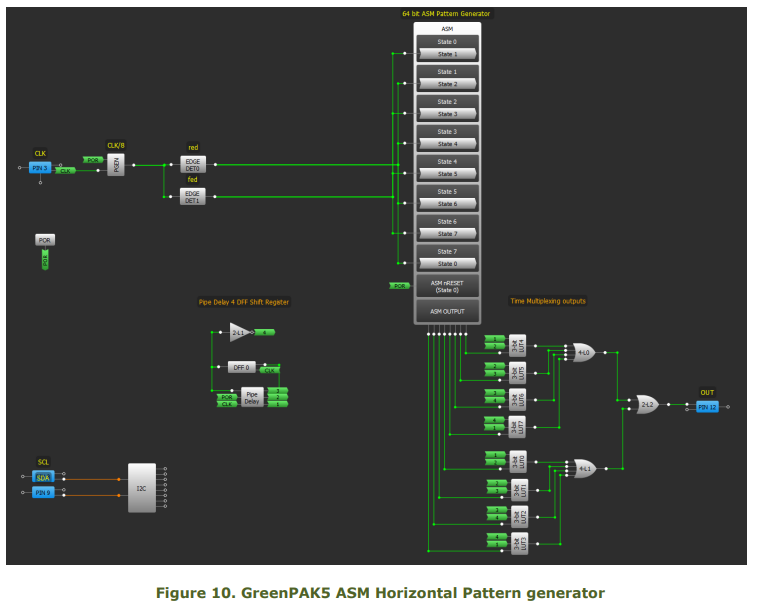
GreenPAK5 – 64-bit Horizontal ASM
In the next two designs we will look at using the ASM to hold the output pattern. ‘Horizontal’ refers to storing the pattern by rows and ‘Vertical’ refers to storing the pattern by columns. The rows are the states and the columns are the outputs. A horizontal design scrolls through the outputs of one row and then moves on to the next row.
In Figure 7, each ASM output is windowed for 1 period by the Pipe Delay, configured as in the previous section. The PGEN generates a pulse every 8 clocks which is used to transition between states.
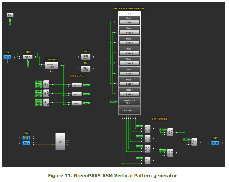
GreenPAK5 – 64-bit Vertical ASM
In the ‘Vertical’ ASM, the design scrolls through the states of one column and then moves on to the next column. In Figure 9, each ASM output is windowed for 8 clock periods by the Gray Code DFFs. The DFF3 generates a pulse every period which is used to transition between states.
Conclusion
There are numerous ways to generate a serial pattern in GreenPAK. The basic forms above provide a starting point and each of them have their pros and cons. While the PGEN is simplest and produces 16 bits, it is available only in GreenPAK4 and GreenPAK5. The FSM and SPI buffer is a great alternative but only available in GreenPAK4, limited to one or two byte length and requires an extra input. If the pattern is short, simply use DFFs in a ring structure and set an initialized value.
There are also state machine alternatives that use DFF’s and LUT’s to create a code that can help you generate a pattern. In this app note, we covered using binary and gray code DFF’s or the register shifting Pipe Delay to traverse states in a particular order. Binary and Gray code yields 2^x pattern bits and the Pipe delay yields 2*x pattern bits where x is the number of DFF’s used. Both gray code and the pipe delay eliminate output glitches that could occur from using binary counting DFF’s.
Select the form that best suits the circuit resources available and the length of data needed to output. Just about any block can store data and there are more than a few ways to send that data out as this app note only covers the simplest of forms. Manipulate or expand by adding more DFF’s, optimize for long run lengths of 1s or 0s, or even re-use components to maximize pattern storage.