Usually, for HV experiments is used so-called ZVS driver, but damage to the mosfets often occurs due to its low efficiency. This is simple, compact, easy to make, and stable during long-term operatin HV Source.
This time I will present you how to make a quality High Voltage source in a very simple way. For this purpose I will use a old PC power supply, but it can also be used new one, whose price is very low, in the range of ten dollars due to mass production nowadays. During the testing I will use several different power supplies with different defined power and brands.
And the best information is that when making these device we will not make complex modifications in the power supply itself, which means that the device will be able to be made by those less experienced in this field. In that way, we will use almost all protection and safety procedures that are taken during the design of these power supplies. These devices are usually full of dust due to the way they work, so I first cleaned it well.
If you want to make a PCB for your project, PCBway is a great choice for you. PCBway is one of the most experienced PCB manufacturing company in China in field of PCB prototype and fabrication. They have a large online community where you can find a Open Source projects, and you can also share your project there. From my personal experience I can tell you that on this community you can find many useful projects
The picture below shows a standard PC power supply circuit, so basically all power supplies are based on the same principle of operation.
Now lets see the basic parts of one PC power supply:
- Input part, symetric rectifier with four diodes and filter capacitors
- Fuse and NTC resistor
- Oscillator integrated circuit(usually TL494)
- Two power switching Transistors or Mosfets
- Switching Transformers (Main transformer is bigger one)
- Shotky diodes , Choke , and output filter capacitors.
If the power supply has its own switch, it is necessary to short-circuit the Green wire with ground (any black wire). In my case, the power supply is activated with its own switch.
And now, the only modification we need to make is to remove the Schottky diodes, which is easiest to do together with the aluminum heatsink. For this operation we usually need a soldering iron with a higher power or a higher temperature at the tip.
After unsoldering the diodes, first we need to carefully examine the PCB with a magnifying glass, and if we made a short circuit during desoldering, repair it. It is good to mention that with this type of modification 4 of the 5 power supplies I owned worked, and one did not start and I needed to bypass the protection circuit, but more on that procedure in one of the next videos.
Next, we will use the secondary of the Main Transformer to drive the High Voltage Transformer.
As can be seen in this case, always one terminal of the transformer is connected to the ground. In all cases, the ground lead will be our one electrode. The other electrode is usually one of the leads next to this one, regardless of whether it is on the left or right side. In these two places we need to solder an insulated wire with a cross section of at least 1.5mm. I use copper wire with a diameter of 2.5 mm insulated with a heat-resistant silicon insulator.
Now we need to somehow conduct these two wires to the outside and connect them to a terminal. Of course, while performing all these operations, the power supply must be disconnected from the mains. Let me also mention that these wires in this case have no function and I can remove all of them, except for the green and one black wire, for the reasons I mentioned before.
And now, a few words about the high-voltage transformer. In my case, it is a transformer-cascade taken from an old CRT monitor, on whose core is wound 7-10 turns of varnished copper wire with a diameter of 1mm or more. On several parts of the coil there are places for taping, so that we can make more precise adjustments depending on the type of power supply. If the number of primary windings of the trafo is well chosen, the device can work for a long time without any heating of the switching transistors. In order not to overload, the number of primary windings should be selected so that the spark does not exceed a length of 5-7 cm.
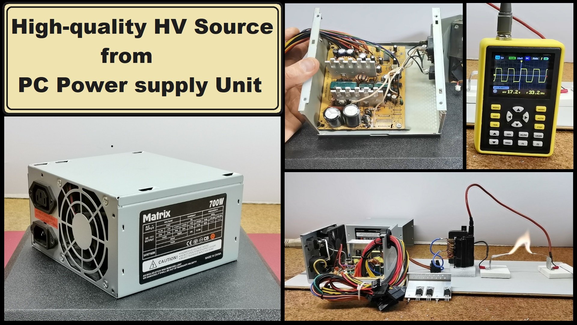
It would be good to look at the shape of the signal at the output of the mains transformer with, and without load. As you can see the shape without load is rectangular with a frequency of 32KHz and a peak to peak voltage of 24V
And finally, a short conclusion: Usually, for HV experiments is used so-called ZVS driver, but damage to the mosfets often occurs due to its low efficiency. I made this device as a basis for future projects related to High Voltage, because it is compact, easy to make, galvanically isolated from the mains and also stable during long-term operation. Although it looks simple, this project should be done very carefully. During testing I damaged two power supplies, one due to overload and the other due to carelessness. After any modification, we should always first assemble the power supply and then test if it works for security reasons. In each test, we first start with the largest number of turns of the primary of the HV transformer, and then gradually reduce.
SAFETY NOTE: Please do not attempt to recreate the experiments shown on this video unless you are familiar with High Voltage Safety Techniques! Direct Current even above 60V maybe lethal, even when the AC supply voltage has been disconnected due to the stored energy in the capacitors.