LED lighting has many benefits over traditional incandescent bulbs, including energy efficiency and power output. However, LEDs turn on instantly, and for those who want to retro-fy their LEDs, this circuit will make an LED slowly turn on and slowly turn off, all in analog circuitry!
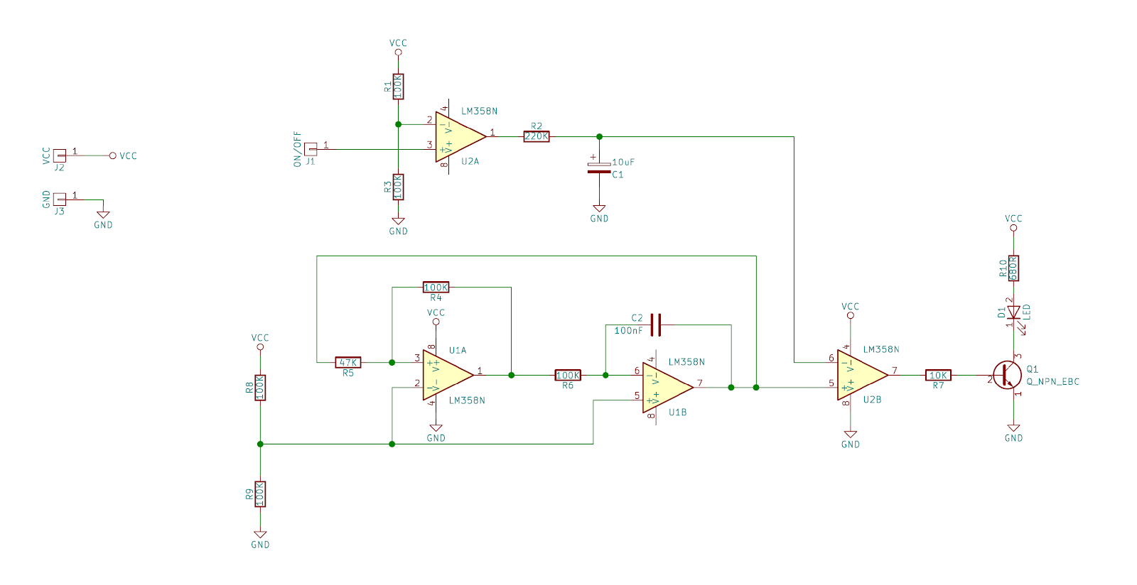
Schematic
How It Works
This circuit is composed of three main sub-circuits: a triangular oscillator, a PWM generator, and a capacitor charge/discharge circuit. The first sub-circuit, the triangular oscillator, is composed of op-amps U1A and U1B with U1B being configured as an integrator while U1A is configured as a Schmitt trigger. The output of the integrator is connected to the input of the Schmitt trigger, which results in four conditions:
- If the output voltage of the integrator goes beyond the upper threshold, the Schmitt triggers output switches low
- If the output voltage of the integrator goes beyond the lower threshold, the Schmitt triggers output switches high
- If the output of the Schmitt trigger is high, the output voltage of the integrator increases steadily
- If the output of the Schmitt trigger is low, the output voltage of the integrator decreases steadily
The result of these four conditions is a continuous triangular waveform on the output of U1B. Incidentally, this oscillator also produces a square wave, which can be found on the output of U1A. This circuit is especially useful for those who want a square wave which is in phase with a triangular wave. But why do we have an oscillator for this LED driving circuit? The answer lies in PWM, pulse width modulation.
When incandescent bulbs turn on and off, they do not do so instantly. Instead, they take time to turn on and off, which is something that modern LED lights do not do. Therefore, to simulate this effect with an LED, we will need a circuit to control the brightness efficiently. One of the most common ways to do this with an LED is with the use of a PWM generator. In our circuit, we take the triangular waveform produced by U1A and U1B and feed this into a comparator U2B. The PWM output produced by U2B will be related to the negative input pin such that a higher voltage on this pin will result in a PWM waveform with a lower duty cycle (i.e., more off than on). The smaller the voltage on the negative input pin, the higher the duty cycle will be (i.e., more on than off). Since the LED is connected to a transistor switch (Q1), which is controlled by U2B, a large voltage on the negative pin will make the LED dimmer, and a small voltage will make the LED brighter.
Now that we have an LED whose brightness can be controlled by a voltage, we need to generate a voltage signal that closely resembles old incandescent bulbs. For this circuit, we use a simple RC circuit, which takes approximately 2 seconds to fully charge/discharge. Therefore, when the input to this circuit (ON/OFF) is connected to GND, the LED begins to turn on, and when the input is connected to VCC, the LED gradually turns off.
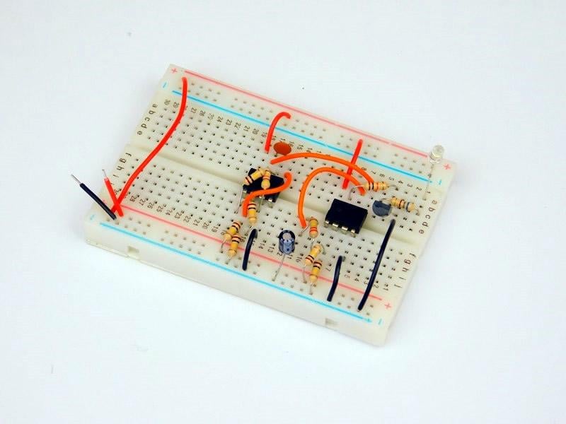
Construction
This project can be built using many different circuit construction techniques including a breadboard, stripboard, matrix board, and even a PCB. Originally, I designed a PCB for this project, but this board failed for unknown reasons. The goal was to turn this circuit into a small module that could be fitted to convert LED lights, and thus all surface mount parts were used. I successfully made the PCB itself, but when turned on, one of the LM358s produced the all magic smoke! Therefore, a breadboard version is shown here instead.