🎯 Project Overview
The Bug in Circuit kit is not just another IoT relay board. It’s a purposefully designed STEM education tool built around an ESP32-based relay board that contains an intentional bug. This tutorial will guide you step-by-step to discover, debug, and fix the issue, helping you learn vital engineering skills like circuit tracing, continuity testing, and fault isolation.
You’ll also learn how to control the relay board with the Arduino IoT Cloud and optionally with Alexa or Google Assistant.
🧰 Parts & Tools Required
- Bug in Circuit IoT Relay Board (1)
- ESP32 (pre-soldered on board) (1)
- USB Cable for Programming (1)
- Multimeter (1)
- Jumper wires (Few)
- Breadboard (optional) (1)
- 5V Power Supply (or USB power) (1)
- Arduino IDE (Installed)
- Arduino IoT Cloud Account (1)
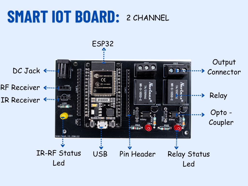
The relay board includes:
- ESP32 MCU
- 2/4/6-channel 12V relay drivers
- Debug point test pads
- Power terminal blocks
- Optional IR/RF receiver headers
However, one of the relay circuits has a deliberate hardware bug. This could be:
- An unconnected GPIO pin
- A missing link between the MCU and relay driver
- A cut or wrong trace
Your goal is to identify and fix this.
🧪 Step 1: Initial Test (and Observe the Bug)
- Connect the board to your PC via USB.
- Open Arduino IDE and install ESP32 support via the board manager.
- Upload the following sketch:
#define RELAY_PIN 13  // Example GPIO

void setup() {
  pinMode(RELAY_PIN, OUTPUT);
  digitalWrite(RELAY_PIN, HIGH);
}

void loop() {
  // Nothing here
}
- Expected behavior: Relay should click ON.
- Reality: Nothing happens — you’ve encountered the bug!
🧰 Step 2: Debugging the Circuit
Now it’s time to think like an engineer.
- Use a multimeter in continuity mode.
- Place one probe on GPIO13 of the ESP32 and the other on the relay input pad.
- If there’s no beep (open circuit), the trace is broken or missing.
- Visually inspect the board for gaps, NC jumpers, or missing resistors.
🔧 Step 3: Fix the Bug
Once you’ve identified the bug:
- Solder a jumper wire or bridge trace between the disconnected pads.
- Re-test with the multimeter to confirm connectivity.
- Power the board again.
- Upload the test sketch — now the relay should click ON.
☁️ Step 4: Control via Arduino IoT Cloud
- Go to Arduino IoT Cloud and create a new Thing.
- Link your ESP32 device.
- Add a Boolean variable named
relayStatus. - Use the following code:
#include "thingProperties.h"
#define RELAY_PIN 13

void setup() {
  pinMode(RELAY_PIN, OUTPUT);
  initProperties();
  ArduinoCloud.begin(ArduinoIoTPreferredConnection);
}

void loop() {
  ArduinoCloud.update();
  digitalWrite(RELAY_PIN, relayStatus ? HIGH : LOW);
}
Now you can toggle the relay from anywhere online!
🔊 Optional: Alexa/Google Assistant Control
- In Arduino Cloud, go to Integrations > Amazon Alexa.
- Link your Arduino account.
- Sync the
relayStatus variable. - Ask Alexa: "Turn on my relay" and watch it work.
💡 Educational Value
This project isn’t just about turning things on and off — it’s about the journey to get there. Debugging is a real skill used by engineers daily, and by tackling a non-working board, students and makers:
- Learn to think critically
- Use measurement tools
- Understand real-world electronics design issues
Workshops at SRM University showed how this approach builds confidence and solidifies hardware knowledge through challenge-based learning.
✅ Conclusion
By intentionally embedding a bug, the Bug in Circuit kit transforms the learning process from linear instruction to active discovery. Whether you're an educator, student, or self-taught maker, this kit will train you to troubleshoot like a pro.
🔗 Learn more at www.anuelectronics.com
Tagline: Find. Fix. Work.