This project includes detailed instructions for assembling the Line Follower Robot, wiring the components, and Arduino code.
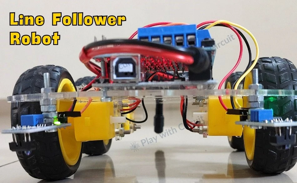
A Line Follower Robot (LFR) is an autonomous robot designed to follow a predetermined path, typically marked as a black line on a white surface or vice versa.
This guide provides a detailed explanation of how to build and operate a line follower robot using Arduino. It covers everything from the basics of line-following technology to assembly and programming.
How the Line Follower Robot Works
The robot detects the line using line sensors. These sensors consist of an IR emitter and an IR receiver.
- White surface: Reflects most of the emitted IR light, detected by the receiver.
- Black line: Absorbs IR light, preventing detection.
The robot uses this principle to differentiate between the line and the surrounding surface.
Navigation Functionality
The robot uses two motors, one on each side of the chassis, for movement control. The signals from the left and right line sensors determine the motor actions:
Forward Movement
- Both sensors are on the white surface (line is in the center).
- Both motors rotate forward.
Turning Left
- Left sensor detects the black line.
- Left motor rotates backward, right motor continues forward.
Turning Right
- Right sensor detects the black line.
- Right motor rotates backward, left motor continues forward.
Stopping
- Both sensors detect the black line.
- Both motors stop.
Components Required for Project
- Arduino UNO R3
- L293D Motor Driver Shield
- Line Sensor Modules (2)
- 12V Li-ion Battery (3)
- Geared Motors (4)
- Robot Chassis
- Wheels (4)
- Jumper Wires
- USB A to B Cable
- Black Tape
Circuit Diagram
Arduino Line Follower Robot Code
/*
Library used: Adafruit Motor Shield library V1 version: 1.0.1
For this code to run as expected:
1.The centre to centre distance between the Line sensors should be 11 to 11.5 cm
2. The width of black tape should be 4.8 to 5 cm
3. The distance of the sensor LED from the flat ground surface should be 2 cm.
*/
#include <AFMotor.h>
// MACROS for Debug print, while calibrating set its value to 1 else keep it 0
#define DEBUG_PRINT 0
// MACROS for Analog Input
#define LEFT_IR A0
#define RIGHT_IR A1
// MACROS to control the Robot
#define DETECT_LIMIT 300
#define FORWARD_SPEED 60
#define TURN_SHARP_SPEED 150
#define TURN_SLIGHT_SPEED 120
#define DELAY_AFTER_TURN 140
#define BEFORE_TURN_DELAY 10
// BO Motor control related data here
// Here motors are running using M3 and M4 of the shield and Left Motor is connected to M3 and Right Motor is connected to M4 using IC2 of the shield
AF_DCMotor motorL(3);  // Uses PWM0B pin of Arduino Pin 5 for Enable
AF_DCMotor motorR(4);  // Uses PWM0A pin of Arduino Pin 6 for Enable
// variables to store the analog values
int left_value;
int right_value;
// Set the last direction to Stop
char lastDirection = 'S';
void setup() {
#if DEBUG_PRINT
  Serial.begin(9600);
#endif
  // Set the current speed of Left Motor to 0
  motorL.setSpeed(0);
  // turn on motor
  motorL.run(RELEASE);
  // Set the current speed of Right Motor to 0
  motorR.setSpeed(0);
  // turn off motor
  motorR.run(RELEASE);
  // To provide starting push to Robot these values are set
  motorR.run(FORWARD);
  motorL.run(FORWARD);
  motorL.setSpeed(255);
  motorR.setSpeed(255);
  delay(40);  // delay of 40 ms
}
void loop() {
  left_value = analogRead(LEFT_IR);
  right_value = analogRead(RIGHT_IR);
#if DEBUG_PRINT
  // This is for debugging. To check the analog inputs the DETECT_LIMIT MACRO value 300 is set by analysing the debug prints
  Serial.print(left_value);
  Serial.print(",");
  Serial.print(right_value);
  Serial.print(",");
  Serial.print(lastDirection);
  Serial.write(10);
#endif
  // Right Sensor detects black line and left does not detect
  if (right_value >= DETECT_LIMIT && !(left_value >= DETECT_LIMIT)) {
    turnRight();
  }
  // Left Sensor detects black line and right does not detect
  else if ((left_value >= DETECT_LIMIT) && !(right_value >= DETECT_LIMIT)) {
    turnLeft();
  }
  // both sensors doesn't detect black line
  else if (!(left_value >= DETECT_LIMIT) && !(right_value >= DETECT_LIMIT)) {
    moveForward();
  }
  // both sensors detect black line
  else if ((left_value >= DETECT_LIMIT) && (right_value >= DETECT_LIMIT)) {
    stop();
  }
}
void moveForward() {
  if (lastDirection != 'F') {
    // To provide starting push to Robot when last direction was not forward
    motorR.run(FORWARD);
    motorL.run(FORWARD);
    motorL.setSpeed(255);
    motorR.setSpeed(255);
    lastDirection = 'F';
    delay(20);
  } else {
    // If the last direction was forward
    motorR.run(FORWARD);
    motorL.run(FORWARD);
    motorL.setSpeed(FORWARD_SPEED);
    motorR.setSpeed(FORWARD_SPEED);
  }
}
void stop() {
  if (lastDirection != 'S') {
    // When stop is detected move further one time to check if its actual stop or not, needed when the robot turns
    motorR.run(FORWARD);
    motorL.run(FORWARD);
    motorL.setSpeed(255);
    motorR.setSpeed(255);
    lastDirection = 'S';
    delay(40);
  } else {
    // When stop is detected next time then stop the Robot
    motorL.setSpeed(0);
    motorR.setSpeed(0);
    motorL.run(RELEASE);
    motorR.run(RELEASE);
    lastDirection = 'S';
  }
}
void turnRight(void) {
  // If first time Right Turn is taken
  if (lastDirection != 'R') {
    lastDirection = 'R';
    // Stop the motor for some time
    motorL.setSpeed(0);
    motorR.setSpeed(0);
    delay(BEFORE_TURN_DELAY);
    // take Slight Right turn
    motorL.run(FORWARD);
    motorR.run(BACKWARD);
    motorL.setSpeed(TURN_SLIGHT_SPEED);
    motorR.setSpeed(TURN_SLIGHT_SPEED);
  } else {
    // take sharp Right turn
    motorL.run(FORWARD);
    motorR.run(BACKWARD);
    motorL.setSpeed(TURN_SHARP_SPEED);
    motorR.setSpeed(TURN_SHARP_SPEED);
  }
  delay(DELAY_AFTER_TURN);
}
void turnLeft() {
  // If first time Left Turn is taken
  if (lastDirection != 'L') {
    lastDirection = 'L';
    // Stop the motor for some time
    motorL.setSpeed(0);
    motorR.setSpeed(0);
    delay(BEFORE_TURN_DELAY);
    // take slight Left turn
    motorR.run(FORWARD);
    motorL.run(BACKWARD);
    motorL.setSpeed(TURN_SLIGHT_SPEED);
    motorR.setSpeed(TURN_SLIGHT_SPEED);
  } else {
    // take sharp Left turn
    motorR.run(FORWARD);
    motorL.run(BACKWARD);
    motorL.setSpeed(TURN_SHARP_SPEED);
    motorR.setSpeed(TURN_SHARP_SPEED);
  }
  delay(DELAY_AFTER_TURN);
}