In this article, we'll learn how to create an alert system text SMS using Arduino and SIM800L module.
In this article, we'll learn how to create an Alert System Text SMS using Arduino and SIM800L Module.
Electronic Components Used in This Project
In several places, security systems are needed to protect rooms. For this, we need to install equipment that protects the place and, for example, generates an alert to notify that the room has been accessed by someone.
One way to solve this problem is to use the Arduino with the reed switch sensor. That is, when someone opens the door, a person will receive an alert via SMS on their cell phone.
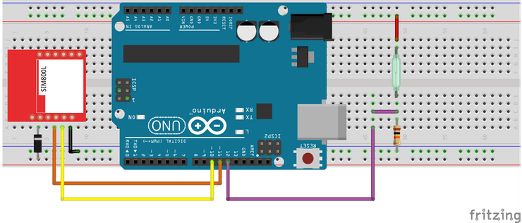
This message will be sent through the SIM800L GSM Module. The circuit is presented in Figure 1.
Figure 1 - Circuit with SIM800L and Reed Switch to detect opened door.
Now, you'll learn how to create the project step by step.
The Step By Step of the Project
First, we'll explain how works the project. You need to install your reed switch sensor and a magnet in your door. And hereafter, you'll connect the sensor in your Arduino System.
When the door is opened, the magnet will move away from the reed switch sensor and it will open. In this way, the system will detect that the door has been opened and will send a SMS through SIM800L for the user.
The circuit in the breadboard is presented below.
Figure 2 - Circuit to detect opened door in the Breadboard.
The Source Code of the Project
Below, you can see the source code of this project. Hereafter, we'll present the step by step of this code.
#include <SoftwareSerial.h>
SoftwareSerial chip(10, 11);

String SeuNumero = "+xxxxxxxxxxxxx";

#define sensor 12

bool ValorAtual = 0, ValorAnterior = 0;

void setup()
{
  Serial.begin(9600);
  Serial.println("Inicializando Sistema...");
  delay(5000);
  chip.begin(9600);
  delay(1000);

  pinMode(sensor, INPUT); //Configura o Pino do Sensor como Entrada
}

void loop()
{
  //Le o valor do pino do sensor
  ValorAtual = digitalRead(sensor);

  if(ValorAtual == 1 && ValorAnterior == 0)
  {
      ClosedDoor();
      ValorAnterior == 1;
  }

  if(ValorAtual == 1 && ValorAnterior == 0)
  {
      OpenedDoor();
      ValorAnterior == 0;
  }

}

void OpenedDoor() //Funcao para enviar mensagem de alerta Umidade Baixa
{
  chip.println("AT+CMGF=1");
  delay(1000);
  chip.println("AT+CMGS=\"" + SeuNumero + "\"\r");
  delay(1000);
  String SMS = "Opened Door!";
  chip.println(SMS);
  delay(100);
  chip.println((char)26);
  delay(1000);
}

void ClosedDoor()//Funcao para enviar mensagem de alerta Umidade Normal
{
  chip.println("AT+CMGF=1");
  delay(1000);
  chip.println("AT+CMGS=\"" + SeuNumero + "\"\r");
  delay(1000);
  String SMS = "Closed Door!";
  chip.println(SMS);
  delay(100);
  chip.println((char)26);
  delay(1000);
}
For this project, we use library SoftwareSerial. The library will be used to communicate the Arduino with SIM800L Module through serial communication.
#include <SoftwareSerial.h>
Next, we'll define what is the pin in the Arduino that will be used like a RX and TX serial communication.
SoftwareSerial chip(10, 11);
Subsequently, we need to create a string and add the mobile number to that string. You must enter the + Country Code and your cellphone number after the country code.
String SeuNumero = "+xxxxxxxxxxxxx";
After, it was defined as the sensor pin and the variables of the code.
#define sensor 12

bool ValorAtual = 0, ValorAnterior = 0;
Finally, is executed the setup function in the Arduino.
The function void setup() and void loop() in Arduino
In the serial communication will be initialized the serial of the Arduino pins (digital pin 0 and digital pin 1) and the virtual serial through the library SoftwareSerial with the object chip.
void setup()
{
  Serial.begin(9600);
  Serial.println("Inicializando Sistema...");
  delay(5000);
  chip.begin(9600);
  delay(1000);

  pinMode(sensor, INPUT); //Configura o Pino do Sensor como Entrada
}
Finally, the sensor pin was defined as a digital input pin. Now, in the void loop function, the system will analyze the sensor state and will send the SMS message for the user.
In the code presented below, the system will read the reed switch sensor and will store its value in the variable ValorAtual.
void loop()
{
  //Le o valor do pino do sensor
  ValorAtual = digitalRead(sensor);

  if(ValorAtual == 1 && ValorAnterior == 0)
  {
      ClosedDoor();
      ValorAnterior == 1;
  }

  if(ValorAtual == 0 && ValorAnterior == 1)
  {
      OpenedDoor();
      ValorAnterior == 0;
  }

}
After, the system will verify what was the value read off the sensor. Therefore, was used two conditions to verify the state of the reed switch sensor.
In this code presented above, you can see the first condition. It will be presented below.
if(ValorAtual == 1 && ValorAnterior == 0)
  {
      ClosedDoor();
      ValorAnterior == 1;
  }
As is possible to see, case the read value of the sensor is equal at 1 and the variable ValorAnterior is equal at 0, the system will enter the condition.
In this way, the system will execute the function ClosedDoor() and will send the message "Closed Door" and hereafter will insert the value 1 for the ValorAnterior variable.
This variable is used to ensure that the code flow enters the condition only once. This prevents the system from sending a message several times, while the door is closed or open.
The other condition has a similar working if compared with the condition presented above.
if(ValorAtual == 0 && ValorAnterior == 1)
  {
      OpenedDoor();
      ValorAnterior == 0;
  }
When the sensor has the 0 value returned by the function, the variable ValorAtual will be 0 and the variable ValorAnterior will be 1. In this way, the system will enter in this condition and will execute the functions.
As is possible see, the function OpenedDoor will be executed to send the "Opened Door" message for the user.
Finally, the user will receive an alert message and will contact the responsible people to verify what is occurring in your sector.
After the system receives the message, the user can verify who accessed the environment.
After the user verifies and closes the door, he will receive a new message of Closed Door.
Therefore, from these alert messages, the user will know when there was an invasion and when the system is no longer detecting the presence of intruders.
Acknowledgment
To finish, we thank you for your reading and the support of PCBWAY.COM for supporting Silício Lab in the production of this article for you.
The Silícios Lab thanks UTSOURCE to offer the electronic components to create this project.