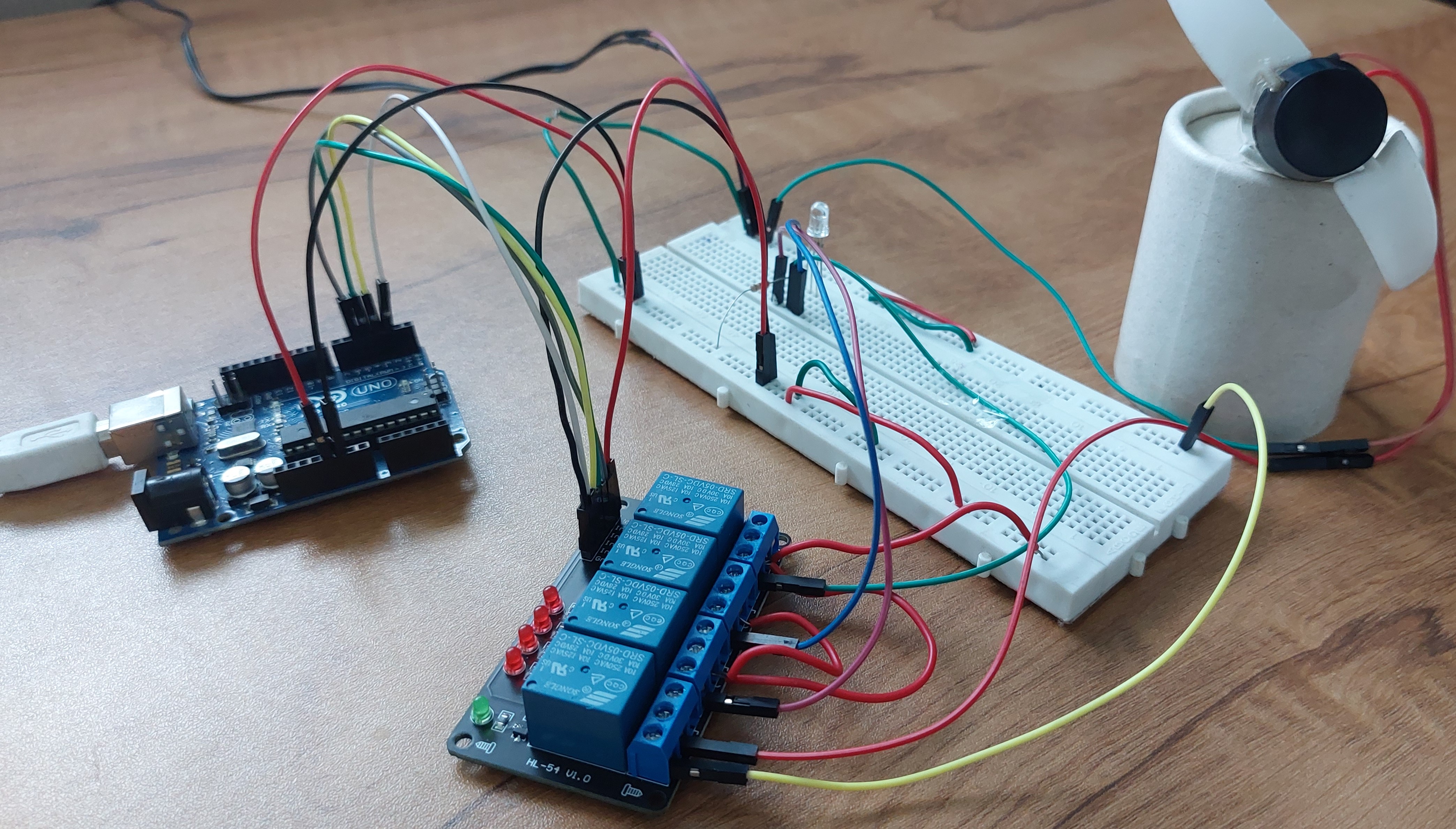
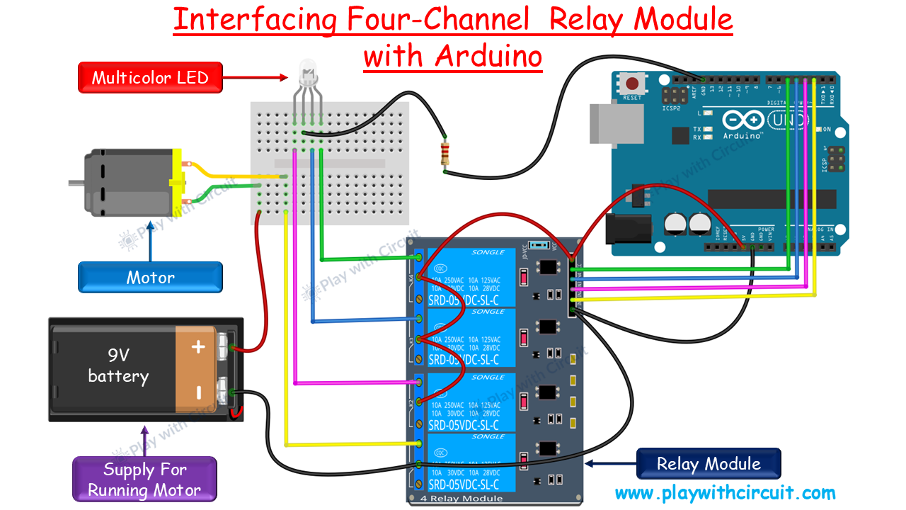
This project demonstrates how to control multiple external loads using an Arduino Uno and a 5V 4-channel relay module. The Arduino controls each relay independently, allowing a DC motor and individual RGB LED channels to be switched using separate outputs.
Relays are useful when an Arduino needs to control electrical loads that require more current or a different voltage than the Arduino GPIO pins can provide.
In this project, we will use an Arduino Uno and a 5V 4-channel relay module to control four separate outputs. The relay module is an HL-52S board containing four independently controlled relays.
Safety: Do not connect mains voltage to the circuit unless you have the necessary electrical knowledge and safety equipment. The demonstration here uses low-voltage DC loads.
How the Relay Works
A relay is an electrically operated switch.
The Arduino sends a small control signal to the relay module. Driver circuitry on the module then energizes the relay coil. The mechanical contacts change position and switch the external load.
This means the Arduino does not have to supply the motor's current directly.
A relay module also contains supporting components such as:
- Transistors for driving the relay coils
- Resistors
- Flyback diodes
- Power LED
- Channel status LEDs
The flyback diode protects the driver circuit from the voltage spike generated when a relay coil is de-energized.
Components Required
- Arduino Uno R3
- 5V 4-channel relay module
- 9V DC motor
- Common-cathode RGB LED
- 9V supply/battery
- Breadboard
- Jumper wires
Relay Module Specifications
Typical specifications for this type of module are:
- Supply voltage: 3.75V to 6V
- Input trigger current: approximately 5mA
- Coil current: approximately 70mA per relay
- Four relay coils: approximately 300mA
- Maximum switching current: 10A
- Maximum contact voltage: 250VAC / 30VDC
The exact ratings can vary between relay module manufacturers, so verify the specifications of the board being used.
Building the Project
Step 1: Connect the Control Side
Connect the relay module to the Arduino:
Relay VCC  → Arduino 5V
Relay GND  → Arduino GND
Relay IN1  → Arduino D2
Relay IN2  → Arduino D3
Relay IN3  → Arduino D4
Relay IN4  → Arduino D5
Step 2: Connect the Loads
Use the relay contacts to switch the external load circuits.
For normally-off operation, use:
External Supply → COM
NO → Load
Load → External Supply return
Repeat the arrangement for the other relay channels as required.
The motor and other loads should have an appropriate external supply.
Step 3: Test the Relay Channels
Because the module is active LOW, pulling an input LOW should activate its relay.
A simple sequence could be:
- Activate Relay 1 and run the motor.
- Turn Relay 1 OFF.
- Activate Relay 2 and illuminate red.
- Activate Relay 3 and illuminate blue.
- Activate Relay 4 and illuminate green.
- Turn all four relays OFF.
The indicator LED on each relay channel should provide a visual indication of its state.
Testing the Relay Without Arduino
The relay board can also be tested manually before connecting it to the Arduino.
Connect push buttons between the relay inputs and ground.
Pressing a button pulls the input LOW:
Button pressed
      ↓
Input LOW
      ↓
Relay activated
      ↓
COM connects to NO
This is a useful troubleshooting method if you are unsure whether the problem is in the Arduino program or the relay module.
Possible Extensions
This basic project can be expanded into a more useful automation system.
Some possibilities include:
- Add push-button control
- Add an OLED display for relay status
- Control the relays using Bluetooth
- Replace the Arduino Uno with an ESP32
- Add Wi-Fi control
- Control the relays from a web interface
- Add temperature or light sensors
- Build an IoT-based appliance controller
For example, an ESP32 could monitor a sensor and activate one of the relay channels automatically when a predefined condition is reached.
Conclusion
A 5V 4-channel relay module provides a simple way to control multiple external circuits from an Arduino Uno.
The most important details in this project are the active-LOW inputs, correct use of the COM/NO/NC contacts, and providing suitable power for the external loads.
For the detailed original tutorial and additional circuit information, see the project documentation on Play with Circuit: https://playwithcircuit.com/interfacing-5v-4-channel-relay-module-with-arduino/