In this project I will show you how to use CanBus Shield for Arduino, how to send and receive specific data. You can easily adopt this project to yours according to your needs.
Why CanBus?
CAN-BUS is a common industrial bus because of its long travel distance, medium communication speed and high reliability. It is commonly found on modern machine tools, such as an automotive diagnostic bus.
In this tutorial I will use SeedStudio CanBus module. It works with SPI interface and with an OBD-II converter cable added on and the OBD-II library imported, you are ready to build an onboard diagnostic device or data logger.
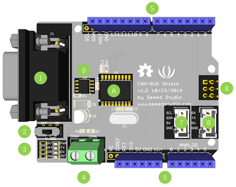
Hardware Overview
- DB9 Interface
- V_OBD
- Led Indicator
- Terminal - CanH, CanL
- Arduino Uno Pinout
- Serial Groove Connector
- I2C Groove Connector
- ICSP Pins
- Tranceiver
Can Bus Messages
Let me explain you a bit about CanBus Messages. Each message consist of an ID and some data. The Id's start at 0x000 and go to 0x7FF in hex or 0 to 2047 in decimal.
The data can be 1 to 8 bytes for each message and each byte can have value from 0 to 255.
CAN buses can operate at several different speeds up to 1 Mbit/s. Typical rates are 100 kbit/s, 125 kbit/s and 500 kbit/s. Slower rates allow for longer length buses. All devices on a bus must transmit at the same speed.
Arduino Code
Let's begin to write our code. I will simply send a potensiometer data and button data to another Arduino over CanBus module. Make sure that you use one Arduino as a Master(Sender) and another as a Slaver (Receiver).
You should download CanBus library from here.
Now we begin to write our Master(Sender) code.
//Canbus Send Data (MASTER)

#include <Arduino.h>
#include <mcp_can.h>
#include <SPI.h>
const int SPI_CS_PIN = 10;
MCP_CAN CAN(SPI_CS_PIN);


int potPin = A0;
int btnPin = 8;
int potValue = 0;
int cantxValue = 0;
int btnValue = 0;
We are including <mcp_can.h> and <SPI.h> libraries for Canbus module. "const int SPI_CS_PIN = 10; "MCP_CAN CAN(SPI_CS_PIN);" codes used for initialisation of module. Lastly we add our variables. potPin, potValue , cantxValue integers are used for reading and sending potentiometer values and btnPin,btnValue integers are used for reading and sending button values.
void setup()
{
  Serial.begin(115200);

  while (CAN_OK != CAN.begin(CAN_500KBPS))  // baudrate 500kbps
  {
      Serial.println("CAN BUS Shield init fail");
      Serial.println("Init CAN BUS Shield again");
      delay(100);
  }
      Serial.println("CAN BUS Initialisation Succesful!");
}
In setup function we start Serial Comminication and check if the module is working properly.
void loop()
{
  potValue = analogRead(potPin);
  btnValue = digitalRead(btnPin);
  cantxValue = map(potValue,0,1025,0,255);
  Serial.print("cantxValue: ");
  Serial.println(cantxValue);
  Serial.print("btnValue: ");
  Serial.println(btnValue);

  //Create CanBus data pack
  unsigned char canMsg[8] = {cantxValue, btnValue, 0x00, 0x00, 0x00, 0x00, 0x00, 0x00};

  //Send Data Construction:  id = 0x07B ---  standart Flame ---  data lenght = 8 ----  stmp:data buf
  CAN.sendMsgBuf(0x07B, 0, 8, canMsg);
  delay(100);
}
In loop function we read potensiometer value and button value. I have mentioned that message value should be in the range of 0 - 255. As you know potensiometer value could be between 0 - 1025. Therefore we are mapping potensiometer value from 0-1025 to 0-255 with the code "cantxValue = map(potValue,0,1025,0,255);".
We are serial printing values to check everthing work fine. Then we create a data pack to send Slaver(Receiver). Data pack can be 8 bytes but we would only use 2 bytes.
After creating data pack, we are passing it to Slaver. "CAN.sendMsgBuf(0x07B, 0, 8, canMsg);" command has 4 arguments which I have explained in the code.
Thats all, we send data to Slaver.You could see full code at the end.
Now, Let's write Slaver(Receiver) code to read our data.
// CAN-BUS Receive Data

#include "mcp_can.h"
#include <SPI.h>
#include <stdio.h>

#define INT8U unsigned char
const int SPI_CS_PIN = 10;
MCP_CAN CAN(SPI_CS_PIN);

INT8U len = 0;
INT8U buf[8];
unsigned char canId;
char str[20];

int btnvalue;
int potvalue;
Again, we are adding necessary libraries.We create variables to assing received data.
void setup()
{

  Serial.begin(115200);

    while (CAN_OK != CAN.begin(CAN_500KBPS))   // canbus baudrate 500kbps
    {
        Serial.println("CAN BUS Shield init fail!!!");
        Serial.println("Init CAN BUS Shield again...");
        delay(100);
    }

    Serial.println("CAN BUS Initialisation Succesful");
}
Again we are checking if the module is working fine.
void loop()
{

      while (CAN_MSGAVAIL == CAN.checkReceive())
        {
      CAN.readMsgBuf(&len, buf);
      canId = CAN.getCanId();
      potvalue = buf[0];
      btnvalue = buf[1];
      }

       Serial.print(" Potensiometer Value : ");
       Serial.print(potvalue);
       Serial.print(" Button Value : ");
       Serial.println(btnvalue);
    }

}
In loop function we are checking if there is any message with the code " while (CAN_MSGAVAIL == CAN.checkReceive())" If there are any receiving data we read sender CanBus ID and we assign buffers to variables to use in functions. Then we Serial print values to check if they are correct.
You could access both Master(Sender) and Slaver(Receiver) codes at the end. Please dont hesitate to ask any questions.