In this project you will learn how to build your own GPS and Arduino vehicle position recorder system.
In this project, you will learn how to build your own GPS and Arduino vehicle position recorder system. Now we will teach you the building process step by step for you to assemble yours.
To construct this project you'll need of this following components:
Now, I'll present the full project for you.
The Project
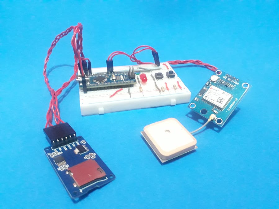
First, we will use some modules to create this project. As provided in the bill of materials, we will use GPS to collect position data and the Memory Card Module to store GPS read positions.
Arduino Nano will be used in this project to perform all control of programming logic.
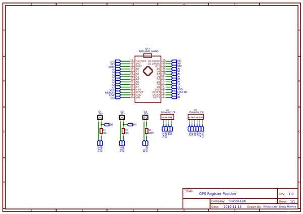
According to this principle of operation, the electronic circuit diagram is presented in Figure 1.
Figure 1 - Electronic Schematic of the GPS Register System.
As is possible to see in this project, there are two buttons. Each button is responsible to start and stop the register processing of GPS positions in the SD Card.
The Red LED will be used to signalize when the data positions are being stored in the SD Card.
According to this circuit at protoboard, the electronic scheme was built. The electronic scheme is presented in Figure 2.
Figure 2 - Schematic circuit of thie GPS Register Position.
Hereafter, was designed the Printed Circuit Board is shown in Figure 3.
Figure 3 - Printed Circuit Board of the GPS Register Position with Arduino.
According to this project, was created the code presented below.
The code is used to communicate Arduino Nano with SD Card Module and GPS Module.
#include <SD.h>
#include <SPI.h>
#include <SoftwareSerial.h>
#include <TinyGPS.h>


SoftwareSerial SerialGPS(4,3);     //Pino 4 - TX do Modulo e Pino 3 - RX do Modulo GPS


TinyGPS GPS;
File myFile;


bool controle = 0;
float lat, lon;
byte pinoCS = 10; //Pin 10 para Nano/UNO

#define INICIA 9
#define TERMINA 5
#define LEDVERMELHO 2

void setup()
{

  SerialGPS.begin(9600);

  Serial.begin(9600);

  pinMode(pinoCS, OUTPUT); //Define o pinoSS como saida
  pinMode(LEDVERMELHO, OUTPUT);

    if (SD.begin())//Inicializa o SD Card
    {
      Serial.println("SD Card pronto para uso."); //Imprime na tela
    }
    else
    {
      Serial.println("Falha na inicializa??o do SD Card.");
      return;
    }
}

void loop()
{

    bool BotaoInicia = digitalRead(INICIA);
    bool BotaoTermina = digitalRead(TERMINA);

    if(BotaoInicia == 1 && controle == 0)
    {
      controle = 1;
      myFile = SD.open("GPS.txt", FILE_WRITE); //Cria e abre o arquivo
      delay(1000);

      myFile.print("Latitude");
      myFile.println("  Longitude");
    }


    if(controle == 1)
    {
        while (SerialGPS.available())
        {
          if (GPS.encode(SerialGPS.read()))
          {
            digitalWrite(LEDVERMELHO, HIGH);

            //latitude e longitude
            GPS.f_get_position(&lat, &lon);

            myFile.print(lat  , 6);
            myFile.println(lon, 6);
            delay(1000);
          }
        }
    }

    if(BotaoTermina == 1 && controle == 1)
    {
      controle = 0;
      myFile.close();
      digitalWrite(LEDVERMELHO, LOW);
    }


}
In the first lines, it will be declared the libraries of the modules and the variables used to manipulate the data in the project, as is shown in the following code.
#include <SD.h>
#include <SPI.h>
#include <SoftwareSerial.h>
#include <TinyGPS.h>


SoftwareSerial SerialGPS(4,3);     //Pino 4 - TX do Modulo e Pino 3 - RX do Modulo GPS


TinyGPS GPS;
File myFile;


bool controle = 0;
float lat, lon;
byte pinoCS = 10; //Pin 10 para Nano/UNO

#define INICIA 9
#define TERMINA 5
#define LEDVERMELHO 2
After this, the system will execute the void setup function. In this function, the system will configure the pins used to connect the LED, button and others like a digital input or output.
Posteriorly, will test the initialization process of the SD Card through the code presented below
if (SD.begin())//Inicializa o SD Card
    {
      Serial.println("SD Card ready for use"); //Imprime na tela
    }
    else
    {
      Serial.println("SD Card initialization failed");
      return;
    }
If the system performs the test and the SD Card initializes correctly, it will print the following message: SD Card ready for use. Otherwise, it will print the message SD Card initialization failed.
After this, the system will enter the void loop function. In this function, the main system logic will be executed.
Firstly, the button START and END will be read. Following, case the START button was pressed, the.txt file will be opened and will be printed the Latitude and Longitude name, to create two columns of data.
The portion of the code is presented below.
bool BotaoInicia = digitalRead(INICIA);
    bool BotaoTermina = digitalRead(TERMINA);

    if(BotaoInicia == 1 && controle == 0)
    {
      controle = 1;
      myFile = SD.open("GPS.txt", FILE_WRITE); //Cria e abre o arquivo
      delay(1000);

      myFile.print("Latitude");
      myFile.println("  Longitude");
    }
After this, the system will enter the next condition presented below, because the variable control is equal at 1.
if(controle == 1)
    {
        while (SerialGPS.available())
        {
          if (GPS.encode(SerialGPS.read()))
          {
            digitalWrite(LEDVERMELHO, HIGH);

            //latitude e longitude
            GPS.f_get_position(&lat, &lon);

            myFile.print(lat  , 6);
            myFile.println(lon, 6);
            delay(1000);
          }
        }
    }
In the condition, the system will set the Red LED and print the latitude and longitude in the text file GPS.txt each one second. The system will store the data position of the GPS until the user presses the End button.
When the end button was pressed, the variable control will be equal at 0, the file will be closed and the red led will be off, as is shown in the portion of the code presented below.
if(BotaoTermina == 1 && controle == 1)
    {
      controle = 0;
      myFile.close();
      digitalWrite(LEDVERMELHO, LOW);
    }
After this, the system back to the loop to begin and execute the code again.
Conclusion
Thus, as is possible to see, the system can be used to store position traveled by the vehicle in a SD Card Module. In addition, this system can be used to monitor the path taken by vehicles carrying loads of values from one location to another.
In this way, the system presents good results to create projects and you can download the files or obtain your own PCB to construct the project with Arduino.
Thanks to the PCBWay for support of our YouTube Channel.
The Silícios Lab also thanks UTSOURCE for providing the electronic components.