Learn how to interface the water level sensor with Arduino
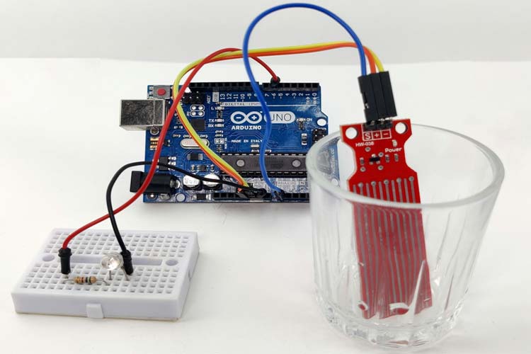
Water tank overflow is a common issue leading to water wastage. While ball valves can prevent overflow, an electronic solution with sensors and automation is preferable for precision. This guide demonstrates interfacing a water level sensor with an Arduino to measure water levels. The working principle of the water level sensor module is very similar to that of a Rain Sensor.
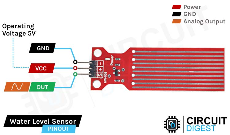
The water level sensor has three pins, operates on 5V, and provides analog data. The VCC pin connects to the 5V power supply, the GND pin connects to the ground, and the OUT pin provides an analog signal between VCC and the ground.
The sensor consists of long conductive plates on a PCB. As water levels rise, the conductivity between the plates changes, altering the output voltage. This change is directly proportional to the water level.
The sensor module includes three pins (VCC, GND, and OUT), a power LED, a transistor, and resistors.
The schematic shows a simple configuration: the transistor collector is connected to 5V, the emitter is connected to the ground via a 100 Ohms resistor, and the conductive plates are connected in series with resistors and the base of the transistor. Increased water levels cause higher output voltage.
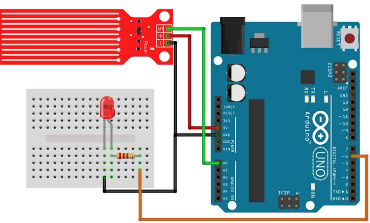
Connect the water level sensor to the Arduino UNO as per the above schematics. The LED is connected to PWM pin 6, and the sensor analog output to the A0 pin, with a common ground and VCC from the Arduino 5V pin. Program the Arduino to adjust the LED brightness based on the water level detected by the sensor.
With this setup, you can efficiently monitor and control water levels, preventing overflow and conserving water.
Here is the code for it. For more details check out the Water Level Sensor Interfacing with Arduino article.
//Arduino water level sensor code


// Sensor pins pin D6 LED output, pin A0 analog Input


#define ledPin 6


#define sensorPin A0


void setup() {


  Serial.begin(9600);


  pinMode(ledPin, OUTPUT);


  digitalWrite(ledPin, LOW);


}


void loop()


{


  unsigned int sensorValue = analogRead(sensorPin);


  if (sensorValue < 540)


    return;


  uint8_t outputValue = map(sensorValue, 540, 800, 0, 255);


  Serial.print(sensorValue);


  Serial.print(" ");


  Serial.println(outputValue);


  analogWrite(ledPin, outputValue); // generate PWM signal


}