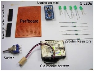
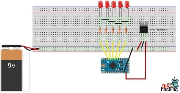
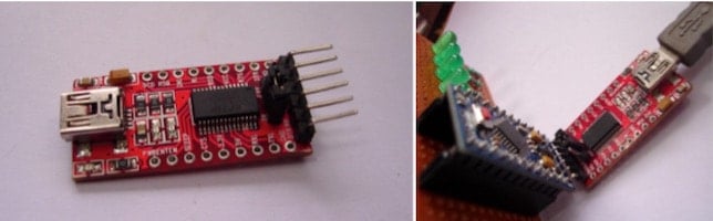
I programmed the Arduino Pro Mini using ‘FTDI USB to serial converter’. You can also program the Arduino Pro Mini using Arduino Uno board. Buy an FTDI USB to serial converter.
Finally, upload the program for Arduino POV display given below:
int delayTime = 1;
int charBreak = 2.1;
int LED1 = 2;
int LED2 = 3;
int LED3 = 4;
int LED4 = 5;
int LED5 = 6;
void setup(){
pinMode(LED1, OUTPUT);
pinMode(LED2, OUTPUT);
pinMode(LED3, OUTPUT);
pinMode(LED4, OUTPUT);
pinMode(LED5, OUTPUT);
}
int a[] = {1, 6, 26, 6, 1};
int b[] = {31, 21, 21, 10, 0};
int c2[] = {14, 17, 17, 10, 0};
int d[] = {31, 17, 17, 14, 0};
int e[] = {31, 21, 21, 17, 0};
int f[] = {31, 20, 20, 16, 0};
int g[] = {14, 17, 19, 10, 0};
int h[] = {31, 4, 4, 4, 31};
int i[] = {0, 17, 31, 17, 0};
int j[] = {0, 17, 30, 16, 0};
int k[] = {31, 4, 10, 17, 0};
int l[] = {31, 1, 1, 1, 0};
int m[] = {31, 12, 3, 12, 31};
int n[] = {31, 12, 3, 31, 0};
int o[] = {14, 17, 17, 14, 0};
int p[] = {31, 20, 20, 8, 0};
int q[] = {14, 17, 19, 14, 2};
int r[] = {31, 20, 22, 9, 0};
int s[] = {8, 21, 21, 2, 0};
int t[] = {16, 16, 31, 16, 16};
int u[] = {30, 1, 1, 30, 0};
int v[] = {24, 6, 1, 6, 24};
int w[] = {28, 3, 12, 3, 28};
int x[] = {17, 10, 4, 10, 17};
int y[] = {17, 10, 4, 8, 16};
int z[] = {19, 21, 21, 25, 0};
int eos[] = {0, 1, 0, 0, 0};
int excl[] = {0, 29, 0, 0, 0};
int ques[] = {8, 19, 20, 8, 0};
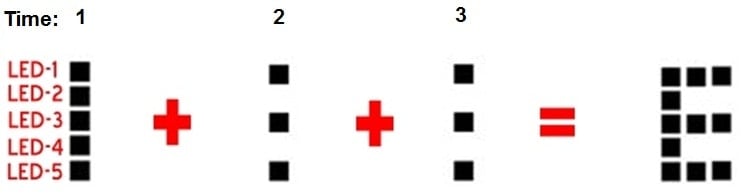
void displayLine(int line){
int myline;
myline = line;
if (myline>=16) {digitalWrite(LED1, HIGH); myline-=16;} else {digitalWrite(LED1, LOW);}
if (myline>=8) {digitalWrite(LED2, HIGH); myline-=8;} else {digitalWrite(LED2, LOW);}
if (myline>=4) {digitalWrite(LED3, HIGH); myline-=4;} else {digitalWrite(LED3, LOW);}
if (myline>=2) {digitalWrite(LED4, HIGH); myline-=2;} else {digitalWrite(LED4, LOW);}
if (myline>=1) {digitalWrite(LED5, HIGH); myline-=1;} else {digitalWrite(LED5, LOW);}
}
void displayChar(char c){
if (c == 'a'){for (int i = 0; i <5; i++){displayLine(a[i]);delay(delayTime);}displayLine(0);}
if (c == 'b'){for (int i = 0; i <5; i++){displayLine(b[i]);delay(delayTime);}displayLine(0);}
if (c == 'c2'){for (int i = 0; i <5; i++){displayLine(c2[i]);delay(delayTime);}displayLine(0);}
if (c == 'd'){for (int i = 0; i <5; i++){displayLine(d[i]);delay(delayTime);}displayLine(0);}
if (c == 'e'){for (int i = 0; i <5; i++){displayLine(e[i]);delay(delayTime);}displayLine(0);}
if (c == 'f'){for (int i = 0; i <5; i++){displayLine(f[i]);delay(delayTime);}displayLine(0);}
if (c == 'g'){for (int i = 0; i <5; i++){displayLine(g[i]);delay(delayTime);}displayLine(0);}
if (c == 'h'){for (int i = 0; i <5; i++){displayLine(h[i]);delay(delayTime);}displayLine(0);}
if (c == 'i'){for (int it = 0; it <5; it++){displayLine(i[it]);delay(delayTime);}displayLine(0);}
if (c == 'j'){for (int i = 0; i <5; i++){displayLine(j[i]);delay(delayTime);}displayLine(0);}
if (c == 'k'){for (int i = 0; i <5; i++){displayLine(k[i]);delay(delayTime);}displayLine(0);}
if (c == 'l'){for (int i = 0; i <5; i++){displayLine(l[i]);delay(delayTime);}displayLine(0);}
if (c == 'm'){for (int i = 0; i <5; i++){displayLine(m[i]);delay(delayTime);}displayLine(0);}
if (c == 'n'){for (int i = 0; i <5; i++){displayLine(n[i]);delay(delayTime);}displayLine(0);}
if (c == 'o'){for (int i = 0; i <5; i++){displayLine(o[i]);delay(delayTime);}displayLine(0);}
if (c == 'p'){for (int i = 0; i <5; i++){displayLine(p[i]);delay(delayTime);}displayLine(0);}
if (c == 'q'){for (int i = 0; i <5; i++){displayLine(q[i]);delay(delayTime);}displayLine(0);}
if (c == 'r'){for (int i = 0; i <5; i++){displayLine(r[i]);delay(delayTime);}displayLine(0);}
if (c == 's'){for (int i = 0; i <5; i++){displayLine(s[i]);delay(delayTime);}displayLine(0);}
if (c == 't'){for (int i = 0; i <5; i++){displayLine(t[i]);delay(delayTime);}displayLine(0);}
if (c == 'u'){for (int i = 0; i <5; i++){displayLine(u[i]);delay(delayTime);}displayLine(0);}
if (c == 'v'){for (int i = 0; i <5; i++){displayLine(v[i]);delay(delayTime);}displayLine(0);}
if (c == 'w'){for (int i = 0; i <5; i++){displayLine(w[i]);delay(delayTime);}displayLine(0);}
if (c == 'x'){for (int i = 0; i <5; i++){displayLine(x[i]);delay(delayTime);}displayLine(0);}
if (c == 'y'){for (int i = 0; i <5; i++){displayLine(y[i]);delay(delayTime);}displayLine(0);}
if (c == 'z'){for (int i = 0; i <5; i++){displayLine(z[i]);delay(delayTime);}displayLine(0);}
if (c == '!'){for (int i = 0; i <5; i++){displayLine(excl[i]);delay(delayTime);}displayLine(0);}
if (c == '?'){for (int i = 0; i <5; i++){displayLine(ques[i]);delay(delayTime);}displayLine(0);}
if (c == '.'){for (int i = 0; i <5; i++){displayLine(eos[i]);delay(delayTime);}displayLine(0);}
delay(charBreak);
}
void displayString(char* s){
for (int i = 0; i<=strlen(s); i++){
displayChar(s[i]);
}
}
void loop(){
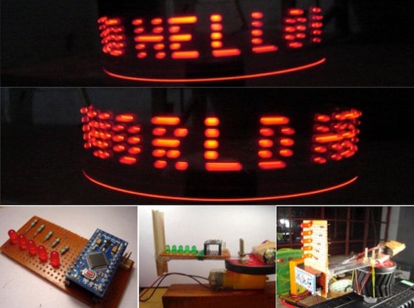
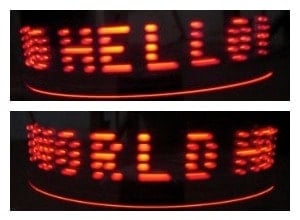
displayString("hello world")
}