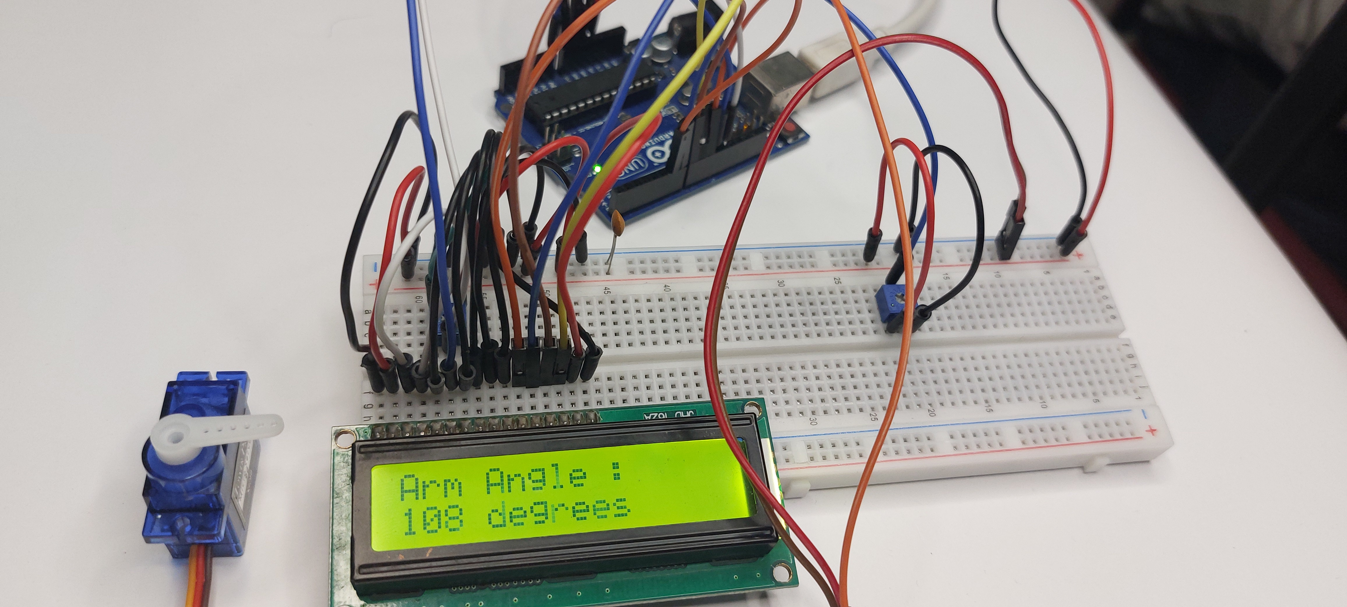
Motor control is an important part of robotics, automation, and embedded-system projects. Although an Arduino UNO can generate the control signals required by a motor, its I/O pins cannot directly provide the current needed by the most motors. A motor driver is therefore required between the Arduino and the motor.
The L293D Motor Driver Shield provides a convenient solution for Arduino-based motor projects. It combines motor-driver circuitry, power connections, and motor connectors on a single board. The shield can be used with DC motors, stepper motors, and servo motors. In this article, we will examine the main features and pin usage of the shield and demonstrate its interface with an SG90 micro servo.
Understanding the L293D Motor Driver Shield
The L293D Motor Driver Shield is an Arduino-compatible expansion board designed to simplify motor interfacing. The board uses two L293D driver ICs. Each L293D contains two H-bridge circuits, allowing current through a DC motor to be switched in either direction. This makes bidirectional motor control possible.
With two L293D ICs, the shield provides four motor channels. These can be used to drive up to four bidirectional DC motors or two stepper motors, depending on the configuration. The board also includes two dedicated three-pin connectors for servo motors.
The shield supports motor supply voltages from approximately 4.5V to 24V, while each L293D channel is rated for up to 600mA continuous current. The actual motor requirements should always be checked before selecting the power supply because the current rating, motor load, and thermal conditions affect practical operation.
Hardware Inside the Shield
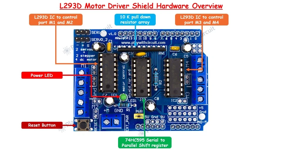
The L293D ICs are the main components responsible for driving the motors. They receive control signals from the Arduino and switch the motor outputs accordingly. This prevents the Arduino's GPIO pins from having to supply motor current directly.
The shield also includes a 74HC595 shift register. This device expands the available control outputs and allows the shield to manage several motor-control signals without consuming an excessive number of Arduino I/O pins.
In addition to the driver ICs and shift register, the board includes a reset button, power indicator LED, pull-down resistor network, external power connector, four motor output terminals, and two dedicated servo headers.
The four motor outputs are labeled M1, M2, M3, and M4. These terminals are used for DC motor and stepper motor connections. Servo motors are connected through the dedicated servo headers rather than through the M1-M4 terminals.
Arduino Pin Usage
The shield occupies several Arduino UNO pins, so it is important to understand the pin allocation before adding other components. The motor shield uses D3, D4, D5, D6, D7, D8, D9, D10, D11, and D12.
D0 and D1 are normally used for serial communication, while D13 is connected to the Arduino's onboard LED. Because most of the digital pins are therefore unavailable or already allocated, the analog inputs can be used as digital inputs when additional buttons are required.
For the servo example described here, A0 is used for the potentiometer and A1 and A2 are used for two push buttons.
Interfacing an SG90 Servo Motor
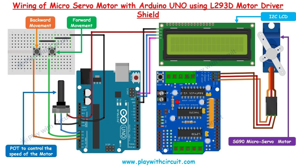
To demonstrate the shield in a practical application, an SG90 5V micro servo can be connected to the first servo connector on the L293D shield. The shield should be mounted directly on the Arduino UNO. If the shield is shown beside the Arduino in a wiring illustration, it is only to make the external connections easier to understand.
Potentiometer Connection
A 10K potentiometer can be added to provide an adjustable analog input for the servo-control program. The middle pin of the potentiometer is connected to Arduino A0, while the two outer pins are connected to 5V and GND.
Rotating the potentiometer changes the voltage appearing at A0. The Arduino reads this analog voltage and can use the resulting value to determine the servo movement speed or another motion parameter defined by the program. This provides a simple way to give the user continuous control rather than relying only on fixed values.
Push Button Interface
Two push buttons are used to control the direction of servo movement. Since the L293D shield already occupies most of the Arduino UNO's digital pins, analog inputs are used as digital inputs.
The first button is connected to A1 and is used for forward movement of the servo arm. The second button is connected to A2 and controls movement in the opposite direction.
When the system is powered up, the servo can be initialized at its center position. Pressing the A1 button moves the servo in one direction, while pressing A2 moves it in the other direction. The program can be designed so that the arm continues moving while the corresponding button remains pressed.
Adding an I2C LCD
A 16×2 LCD with an I2C interface can be added to provide visual feedback. The LCD's VCC is connected to Arduino 5V and its GND is connected to Arduino GND. The SDA and SCL lines are connected to the corresponding SDA and SCL pins of the Arduino UNO.
The display can be used to show information such as the current servo direction, movement status, position, or the speed value obtained from the potentiometer.
Using an I2C display is particularly useful in this project because it requires only the SDA and SCL communication lines instead of consuming several additional Arduino digital pins.
How the Servo Control Works
When the Arduino starts, the servo is initialized to a known center position. The controller then continuously reads the two push-button inputs and the potentiometer connected to A0.
The buttons determine the direction in which the servo should move. The potentiometer provides a variable analog value that can be mapped to the desired movement speed or timing. The Arduino generates the appropriate servo control signal through D10, which is connected to SERVO_1 on the motor shield.
This arrangement provides a simple interface for experimenting with servo-based mechanisms such as pan-and-tilt systems, small robotic arms, automated switches, and other positioning mechanisms.
Power Supply Considerations
The servo headers on this shield obtain their power from the Arduino's 5V supply. This can be suitable for a small SG90 servo, but the current requirement of the connected servo should always be considered. Larger servos can draw substantially more current, particularly during startup or when operating against a mechanical load.
The shield also provides an EXT_PWR connection for supplying power to the motor section. When an external supply is connected through this input, the PWR jumper must be removed according to the shield's power configuration.
Leaving the jumper installed while using an external motor supply can connect the power sources incorrectly and may result in a short circuit or damage to the Arduino and shield.
Extending the Project to Other Motors
The servo interface described above represents only one application of the L293D Motor Driver Shield. The same board can be used for DC motor speed and direction control as well as stepper motor operation.
For example, a DC motor can be connected to one of the M1, M2, M3, or M4 outputs and controlled using the shield's H-bridge circuitry. A 28BYJ-48 5V unipolar stepper motor can also be connected using two motor channels, allowing the Arduino to control its stepping sequence, direction, and speed.
The wiring, library configuration, and programming approach for these motors are different from the servo implementation, so they are not reproduced here. For the complete DC motor and 28BYJ-48 stepper motor connections, Arduino code, library information, and detailed working explanation, refer to the L293D Motor Driver Shield tutorial on Play with Circuit.
Conclusion
The L293D Motor Driver Shield provides a practical way to experiment with several types of motors using an Arduino UNO. Its two L293D driver ICs provide four motor channels, while the dedicated servo connectors simplify the connection of standard hobby servos.