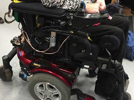
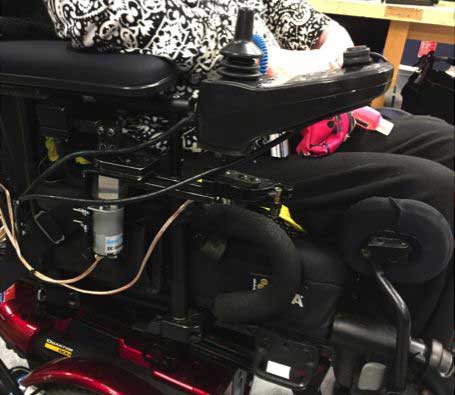
A motorized wheelchair controller mount that can be moved aside with the push of a button to help with accessibility.
This was an Arduino wheelchair project we developed for Principles and Practices of Assistive Technology (PPAT) in Fall 2016 at MIT. We made an Arduino-based motorized wheelchair controller mount for our client, Lisa. She lives at the Boston Home, a center for people with progressive neurological diseases, and has Multiple Sclerosis.
With her old controller mount, she would often bump into sinks and tables because the controller was difficult to push out of the way and jutted out, preventing her from getting as close as she wanted. She wanted a method to move the mount out of the way easily so that she could access sinks and tables. Our solution was this Arduino wheelchair project, that is to create a motorized controller mount which uses a DC Gear Motor and a microcontroller (Arduino UNO) so that Lisa can move the mount with the push of a button. One button press moves the mount away from her, and another press moves it back in front of her. You can watch a video of our device in action below.
We understand that this is not just a problem faced by Lisa alone. A large number of powered wheelchair users face this and similar problems all over the world. We created this Arduino wheelchair tutorial with open source designs for anyone who wants to replicate the project. You can find all the relevant documentation for this project on the Wiki page, including code and design files. In this tutorial, we will try to show you the steps for creating the same.
According to Lisa, "it works just like I'd imagined."
Parts Required for This Arduino Wheelchair Project
We ensured that the parts used for our Arduino wheelchair prototype were common and easily available. Here is a comprehensive list of all the parts with their specifications.
- 1” Aluminum 6061 Extruded Bar stock
- Scrap piece of steel sheet metal 1.1 - 1.2mm thick
- Cytron 12V 17RPM 194.4oz-in Spur Gearmotor
- Motor mount bracket
- Screws and nuts - multiple sizes
- set screw: 8-32 size and thread
- Heavy duty limit switch
- Arduino UNO(we used this as we had one lying around. You can use a smaller board such as Arduino Nano if you like)
- L293D motor driver IC
- LM2596 buck converter IC
- LM7805 voltage regulator IC
Manufacturing the Mechanical Parts
There are two mechanical parts that need to be manufactured for this Arduino wheelchair project. One out of steel sheet metal and another from the extruded aluminum bar. The CAD files for the two parts are available for
download.
The process for machining the aluminum part: The aluminum part was machined from 1” Aluminum 6061 Extruded Bar stock. First, the stock was milled to create a 1”x1”x1” cube. A ½” end mill was used to cut a centered .52” wide groove, .375” deep to fit around the bar of the joystick mount. A .325” deep, hole ½” in diameter was then drilled through the center of the groove to fit around the nut that holds the bar in place. Subsequently, a hole was drilled to fit around the motor shaft, which is 6mm in diameter. To connect this part to the motor, a set screw hole was drilled and tapped to accommodate a set screw of size and thread 8-32.
Schematic
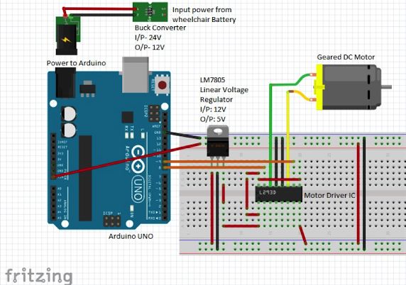
We used an Arduino UNO as the controller along with an L293D motor driver IC, LM2596 DC-DC buck converter module, 7805 voltage regulator IC, and a limit switch. A full schematic of the electronics is available below:
The device is powered by the wheelchair battery, which is a 24V, 36Ah lead acid battery. The Arduino controls the motor based on inputs from a button, a limit switch, and inbuilt timing constraints. The LM2596 buck converter IC steps down the 24V supply from the wheelchair battery to 10.5V, which is used to power the Motor and Arduino. The LM7805 voltage regulator IC steps down the 12V supply from the Vin pin of the Arduino to 5V, which is then used to bias the L293D motor driver IC. Pins 12 and 13 of the motor driver are connected to a common ground with the Arduino to ensure that our system has a stable reference voltage level. Pins 11 and 14 provide the output signal to the DC motor, whereas the pins 10 and 15 provide the motor driver with the data signals from the Arduino, which are used to select whether the motor is rotated clockwise or anti-clockwise.
The limit switch sends a signal to the Arduino when pressed against the body of the device. This signifies the swung-out position of the wheelchair arm. To bring the wheelchair arm back to its initial position, we use a timed approach. The motor is turned on for a set amount of time, which was measured, to move the arm forward. You can find a more detailed description of how the Arduino controls the motor on the Code page.
The Code
The code for our Arduino wheelchair project initializes the mount to the forward position based on the limit switch attached to the mount. When the button is first pressed, the motor rotates clockwise and the mount is pushed out of the way until the limit switch fixed under the mount is closed. When the button is pressed again, the motor rotates in the counter-clockwise direction for 2.15 seconds, which brings the joystick mount back to the original position. The code can be seen here:
int motorforward =8;
int motorbackward=9;
int limit =3;
int button=2;
int delaytime=2150;
int torque=200;
boolean retracted;
void setup() {
// initialize the arm to a state which we know, gearmotor doesnt provide feedback
// we will do this by moving the arm back until it hits the limit switch.
pinMode(limit, INPUT);
pinMode(button, INPUT);
pinMode(motorforward, OUTPUT);
pinMode(motorbackward, OUTPUT);
analogWrite(motorbackward,torque);
while(digitalRead(limit)==0)
{
//loop until back limit switch is pressed
delay(3);       //wait 3ms and check again
}
digitalWrite(motorbackward,LOW);
retracted=true;

//now that the position is known, the main loop can begin.

}

void loop() {
if(digitalRead(button)==1)
{     // enter this big loop if button is pressed
if(retracted)
{
analogWrite(motorforward, torque);    //move arm forward
delay(delaytime);                     //run motor for delaytime/1000 sec
digitalWrite(motorforward, LOW);      //stop motor after switch is pressed
retracted = false;                    //remember that arm is now out
}
else                    //if not retracted do the following
{
analogWrite(motorbackward, torque);   //set motor to move arm backward
while(digitalRead(limit)==0)          //loop until inner limit switch is pressed
{
delay(3);                           //check switch every 3ms
}
digitalWrite(motorbackward, LOW);    //srop motor after switch is pressed
retracted = true;                  //remember that arm is now in
}
}
delay(10);              //wait 10ms, before checking button again.
}
Save the file and open it using the Arduino IDE which can be downloaded here. Connect your Arduino board to the computer via the USB provided. Ensure that the correct board is selected on the 'boards' menu under the 'tools' dropdown. A more clear description on how to upload code to arduino is available here if you're new to this.
Housing and Mounts
Electronic components were housed in a box laser cut from 3.4mm thick black acrylic and held together with epoxy. The plans for the box are shown below, and you can find them
here. The inner dimensions are 4 x 7 x 5 (in cm). Alternatively, you can custom design one for laser-cutting
here.
The electronics box was taped to the back of Lisa's wheelchair. If you can find a better spot for mounting this please let us know in the comments! Three pairs of wire were fed through the holes in the box - one for the 24V wheelchair battery, and one to the motor, and one to the limit switch. The wires to the motor and limit switch were tied together with zip ties and routed to the front of Lisa's wheelchair, where they were soldered onto the motor and onto the limit switch. Moldable putty and heat shrink tubing was used to protect the solder connections.
Ready to Roll! You're all set and ready to roll, power it up and test out the shiny new mechanism that you've just put together! Like and share this if you think it's helpful. Hope this reaches the community of powered wheelchair users.
Make sure to check out more resources for people with different abilities: