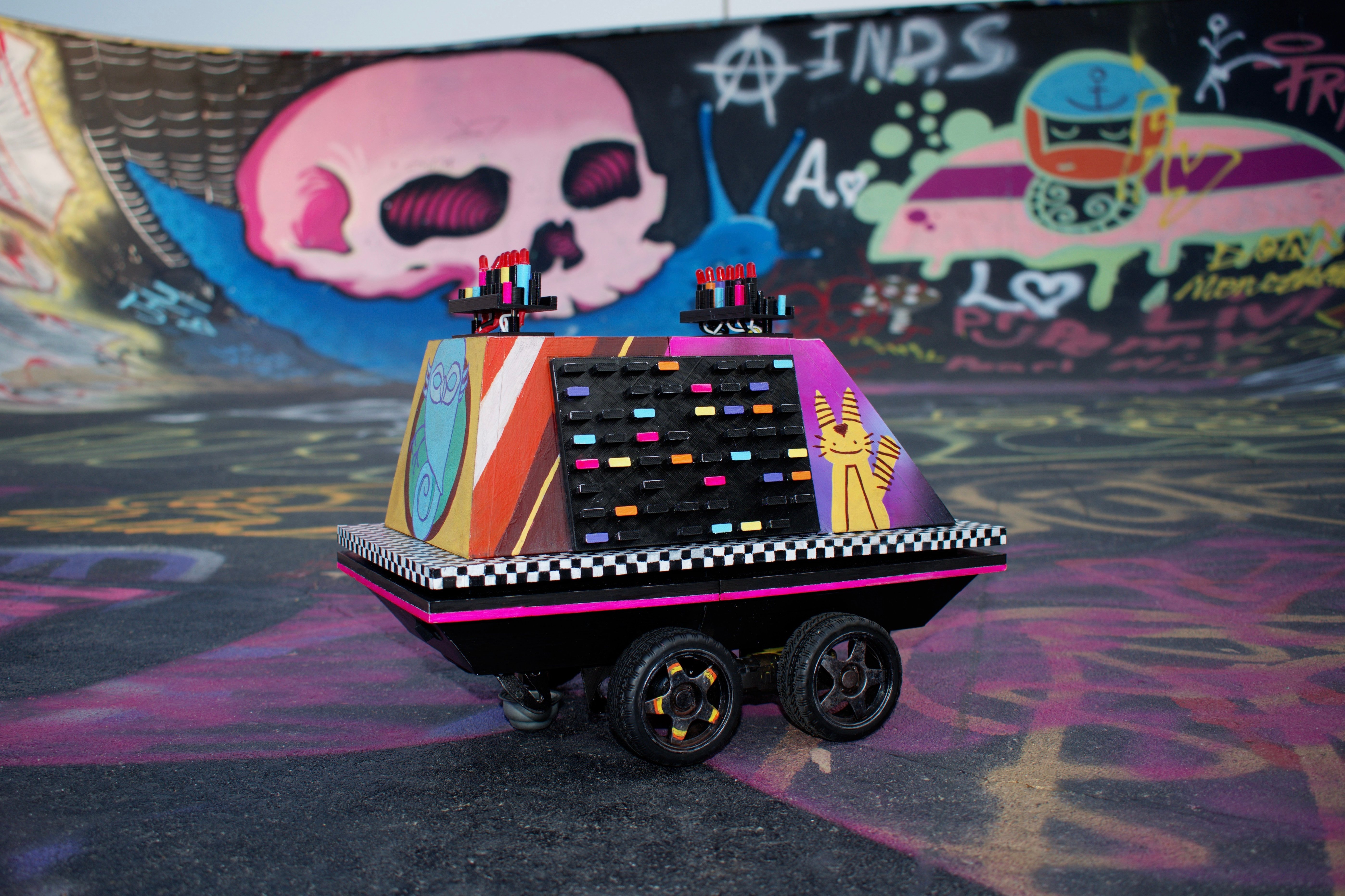
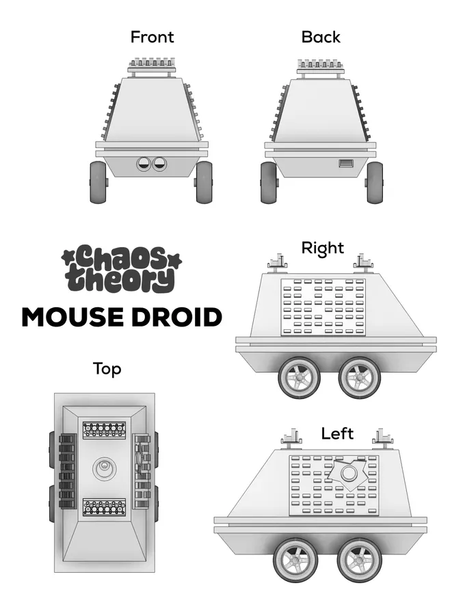
This is a self-driving, screaming, partying mouse (MSE-6) droid.
The idea behind it was simple: what if Sabine Wren adopted a mouse droid? I think it's obvious that she would graffiti it up and splice in a rave mode.
3D File Modifications
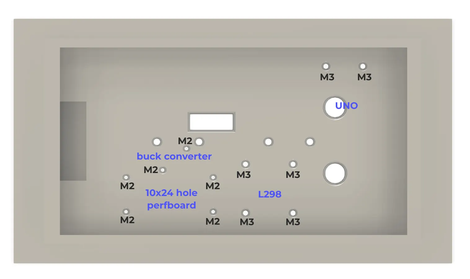
Before you print, think about how you will adhere the electronics to the base. I'm sure you could get away with hot glue and a prayer, but I used nylon standoffs and heat-set inserts for stability. If you're doing the same, you can use the holes in my design, or if you're using different components, please model your own.
If you're using a different rocker switch than I am, you need to adjust the mounting hole size.
Fusion360 file included with the zip pack in the next step.
Printing
Download the 3D files for the project. Included are:
- Bottom half
- Top half
- Left greeblies
- Right greeblies
- Button
- Top greeblies - base (PRINT TWICE)
- Top front greeblies - LEDs
- Top back greeblies - LEDs
- Back wheel mount (PRINT TWICE)
Slice them according to your printer's needs. I printed with 10% infill - make sure to keep it light.
Print away!
Print Assembly
*NOTE* You may choose to not assemble this all before painting to avoid having to mask later on. That's fine.
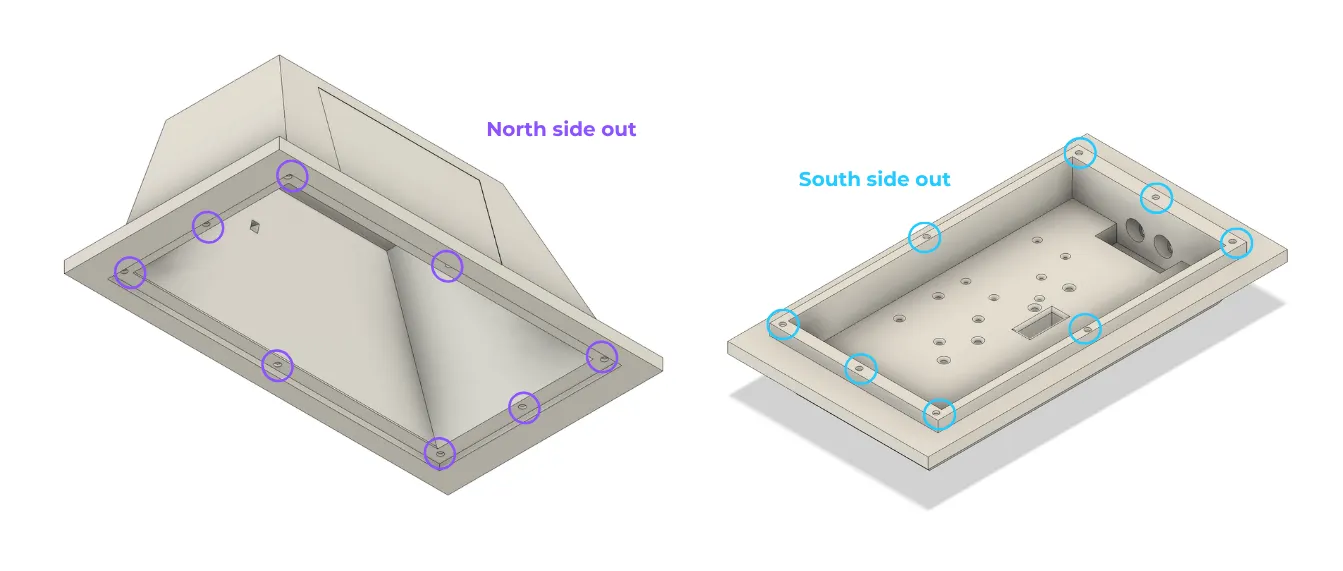
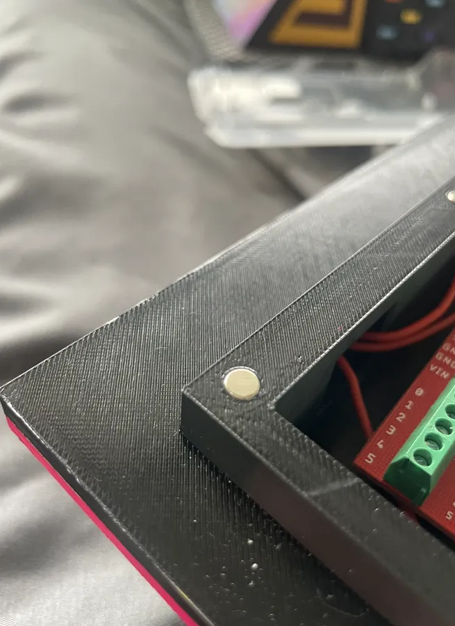
- Add magnets to the top and bottom halves. Make sure to align the polarity correctly so that the top half snaps onto the bottom half (i.e. opposite polarities are facing outward).
- The magnets friction-fit in. Use a flat surface like a ruler to press them down.
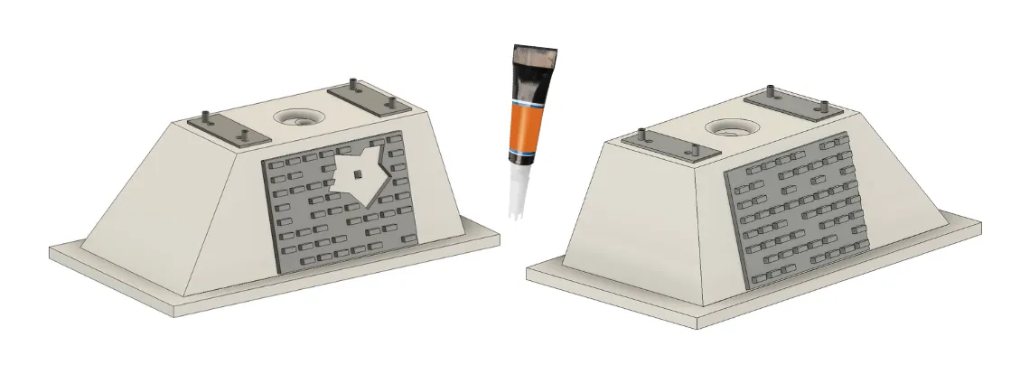
- Glue the top greeblies onto the top half of the droid, settling them in the cavities and aligning the holes.
- Glue the side greeblies onto the cavities on the side, making sure they go on the correct sides.
Caster
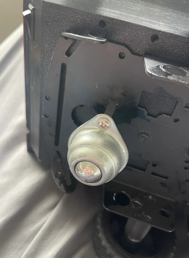
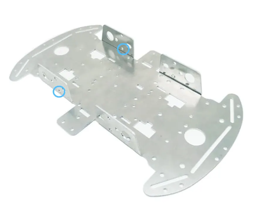
Screw the caster onto the female end of the metal standoffs with 2 M3 bolts.
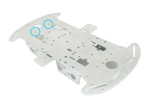
Put the male ends through the holes shown, and secure in place with nuts.
Aluminum Chassis
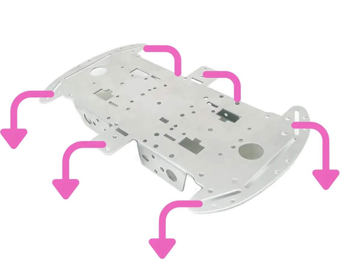
- Bend the flaps of the chassis down. Press against a sturdy surface to help!
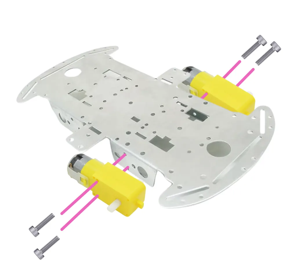
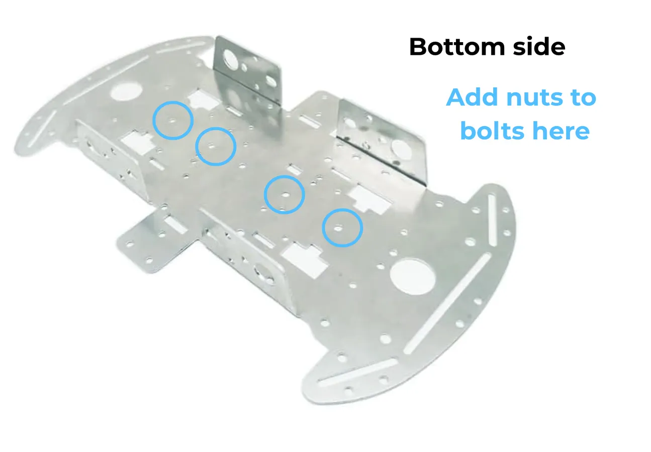
- Using 25mm M3 bolts, screw in the two TT yellow gearbox motors into the chassis (see diagram) and secure them with nuts.
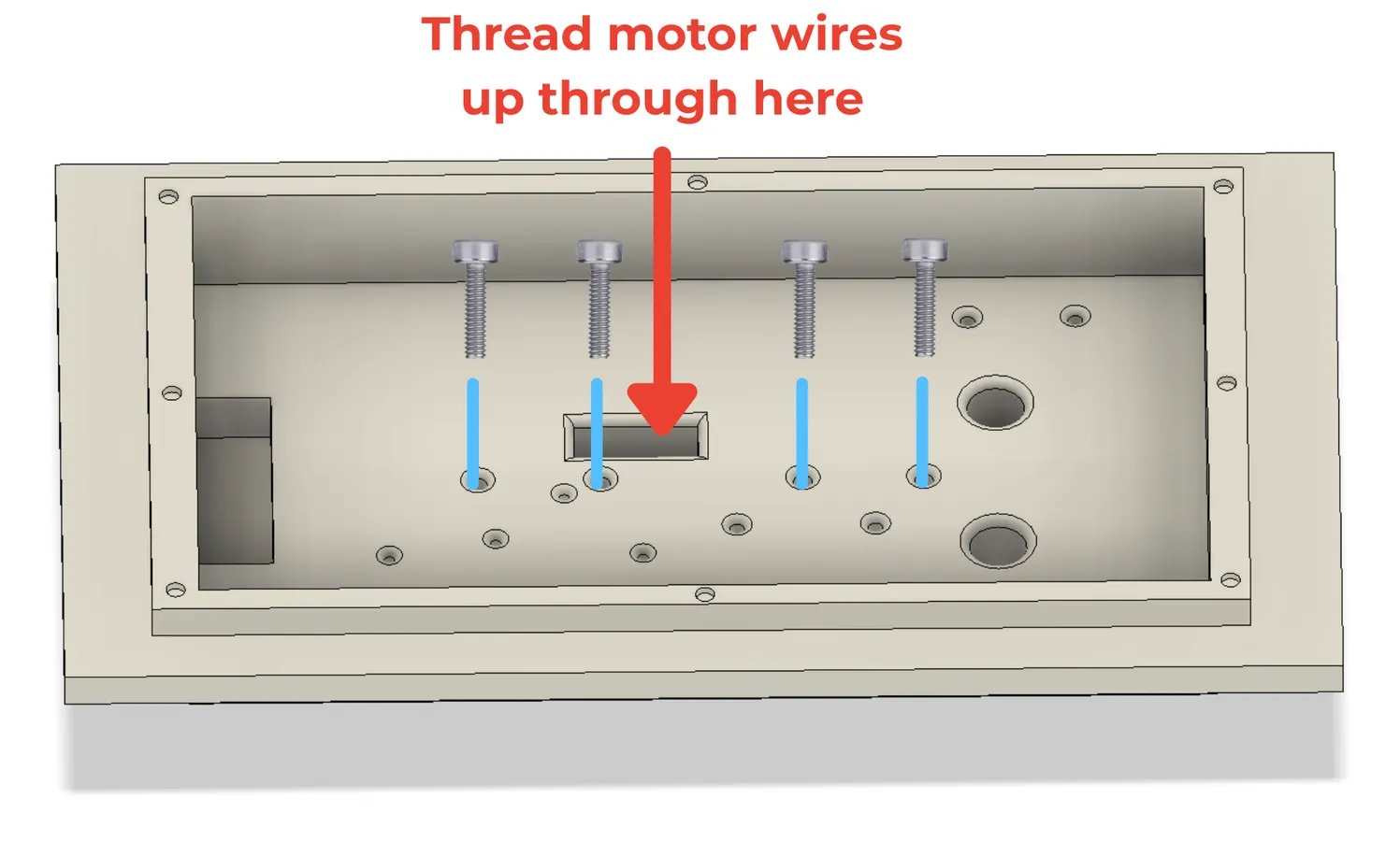
- Thread the TT motor wires through the large rectangular hole in the 3D printed "Bottom Half".
- Using 25mm M3 bolts, screw the chassis into the 3D printed "Bottom Half". The TT motors should be on the same side as the two big holes in front of the 3D print.
Back Wheels
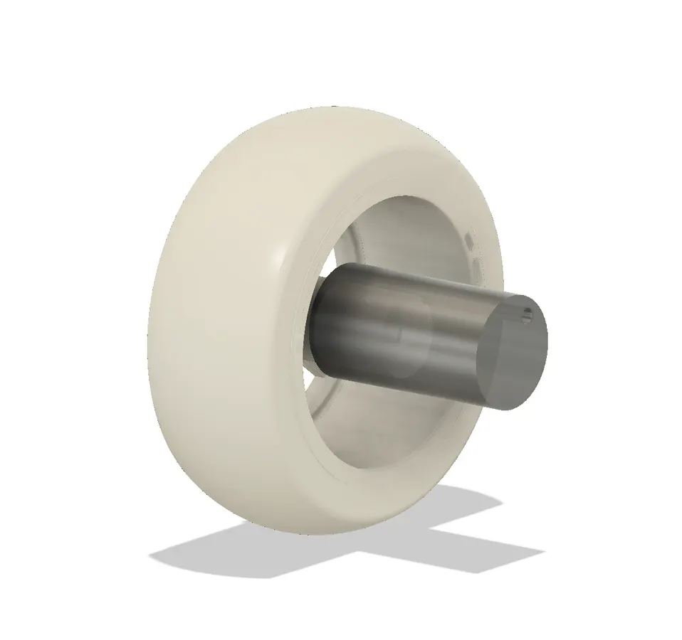
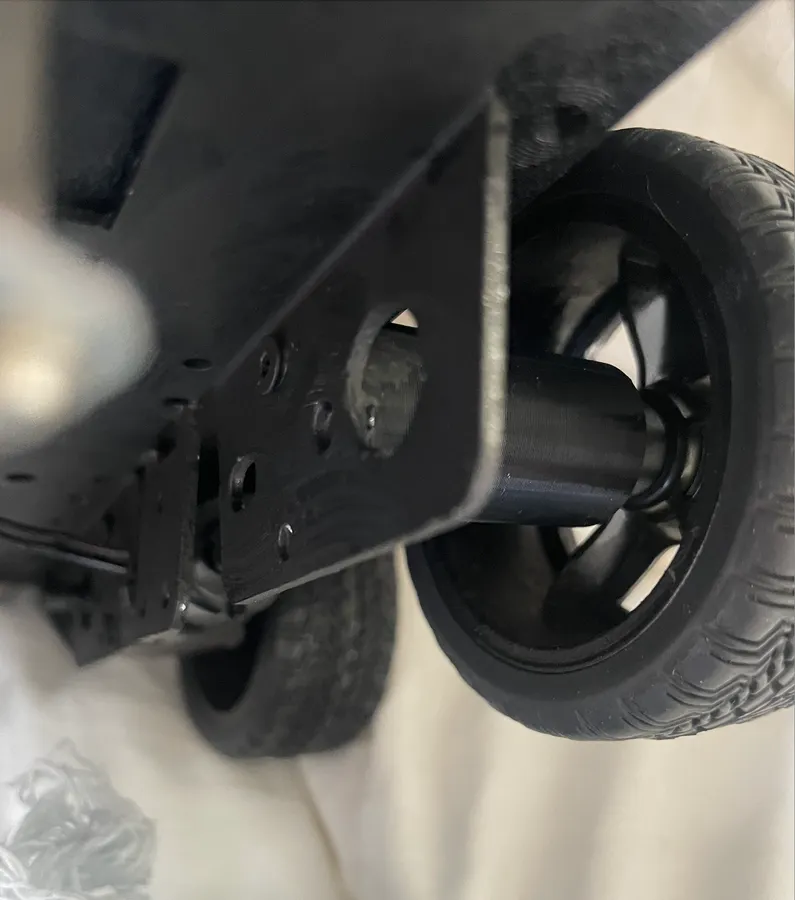
The back wheels are not actually functional. The friction of adding them makes it too hard for the motors to get enough torque, so these are added strictly for aesthetic purposes. They will be lifted a few mm off the ground and wont spin (the back is supported by the caster.)
Find the same holes you used in the previous step to attach the motors but on the backside. You will be using the top hole only.
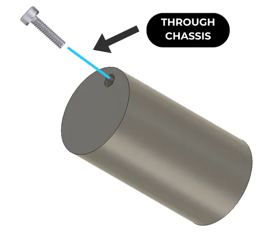
Use a 10 mm M3 bolt to screw into the wheel adapter from the inside of the chassis outward. It is self tapping so might take a bit of effort and precision to do this. Do the same on the other side.
The back of the wheel goes inside the adapter. It should friction fit in.
Plan Decorations
Figure out how you want to paint your droid!
Attached to this step:
- A "Sabine Wren Moodboard" to give you inspiration.
- A blank file for you to sketch over and plan your colours. I like doing this on Procreate on my iPad, but you can definitely print it out and colour the analog way if you'd prefer.
Upload Sound Files
- Download the sound files from the Gumroad link where you got the 3D files.
- Make sure your microSD card is formatted to FAT-32.
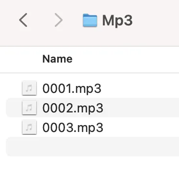
- Create a folder called "Mp3" in your root folder.
- Upload the attached sound files into the "Mp3" folder.
- Make sure to keep the names 0001.mp3, 0002.mp3, respectively.
- Add a party song of your choice to the folder and name it 0003.mp3.
- Eject and then put your microSD card into the DF Player.
Tip: DF Players seem to like it better when you upload the files in order (0001.mp3 first). No idea why.
Circuit Overview
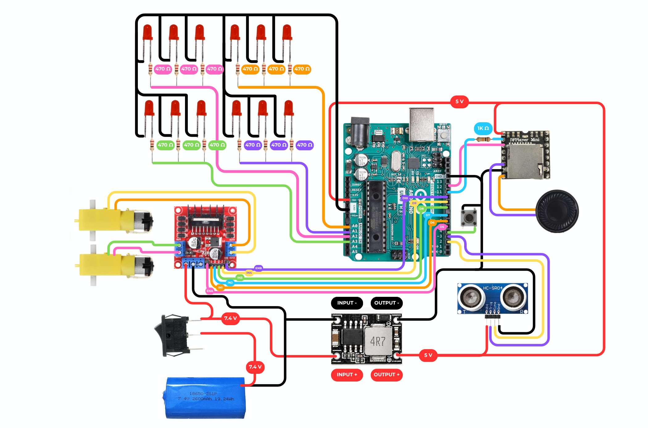
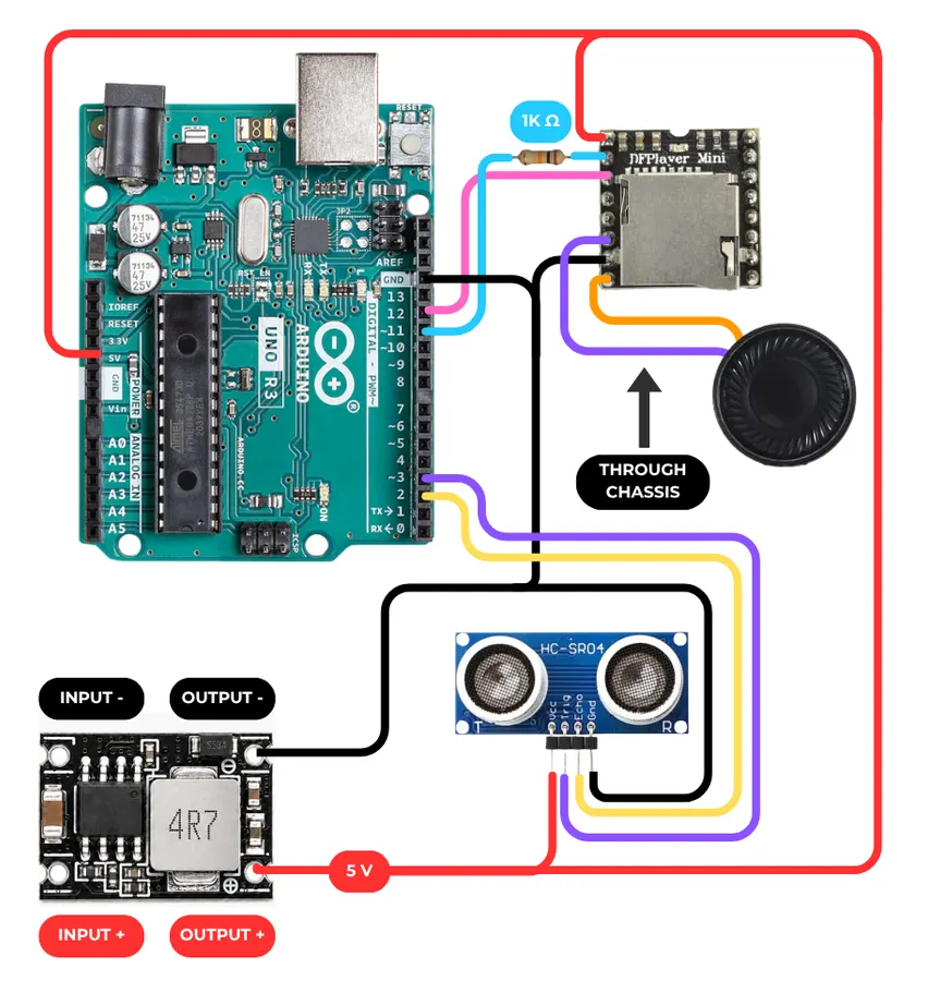
The next steps walk you through the circuit. Here is the overall diagram to give you the full picture before you start; it's detailed, so make sure to download it to see the smaller text. You don't, however, need to read it to follow along.
I recommend you lay out the components that go on the droid floor (battery, motor driver, UNO, buck converter) out loose inside the droid so you know how much wire you need to reach each component.
Modify and Upload Code
Open the code file from Gumroad in Arduino IDE. Change line 99 to be the duration of your party song, then upload the code to your board.
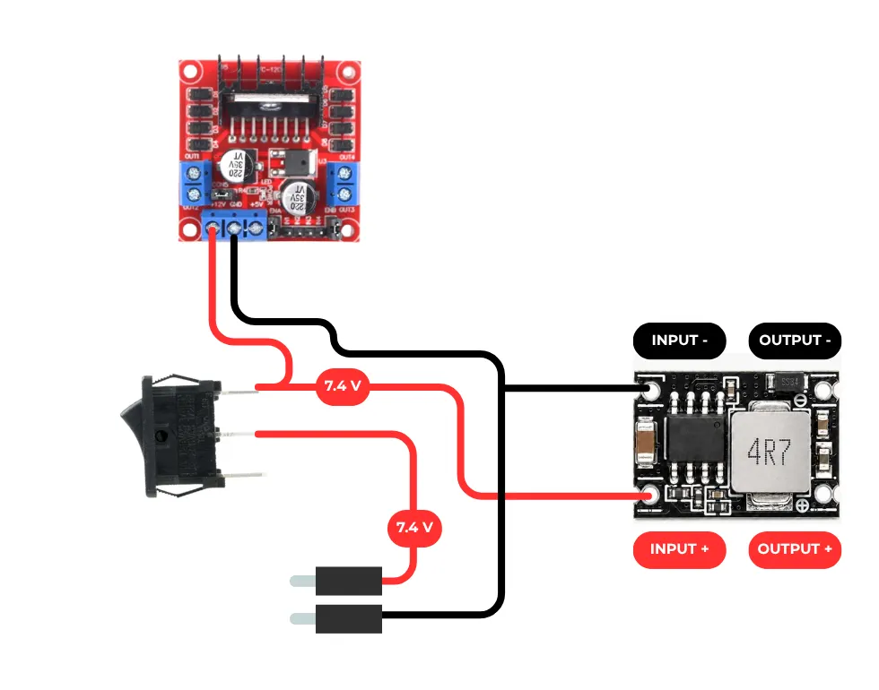
7.4 Volt Section
- Prep the cables and components. The wires that attach to the battery's wires need to have male Dupont ends. Use a crimper to add a double head on OR use existing jumper wires.
- Solder the following components together (with the battery unplugged pls)
- Important: put the switch in the droid (the rectangular slot on the back of the bottom half) BEFORE you solder the wires to the buck converter, or you won't be able to put it in.
- BAT+ to switch input
- Switch output to both motor driver 12V and to buck converter input +
- BAT- to both motor driver - and to buck converter input -
Motor Driver
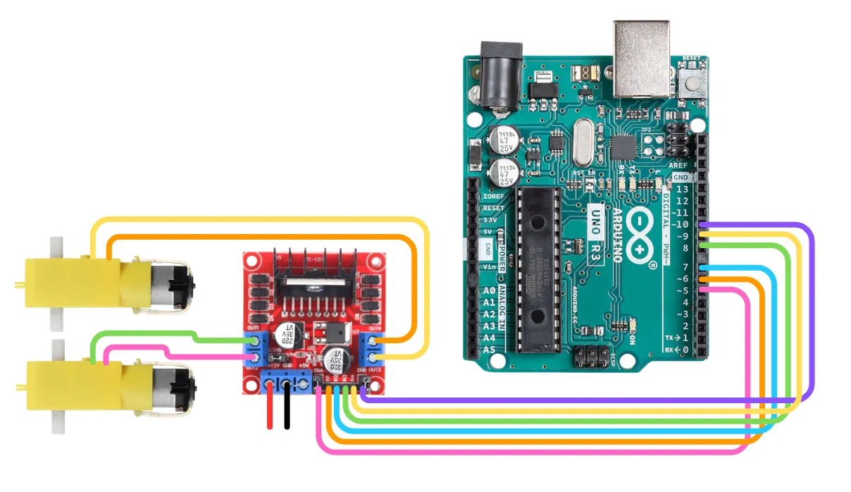
Connect the motor driver to the UNO and the motors. If you're using a screw shield for the UNO, no soldering will be required at this step.
- ENA to D5
- IN1 to D6
- IN2 to D7
- IN3 to D8
- IN4 to D9
- ENB to D10
- OUT1 to left motor + wire
- OUT2 to left motor - wire
- OUT3 to right motor + wire
- OUT4 to right motor - wire
Your 12V and GND motor driver pins should already be connected from the previous step.
5V Rail
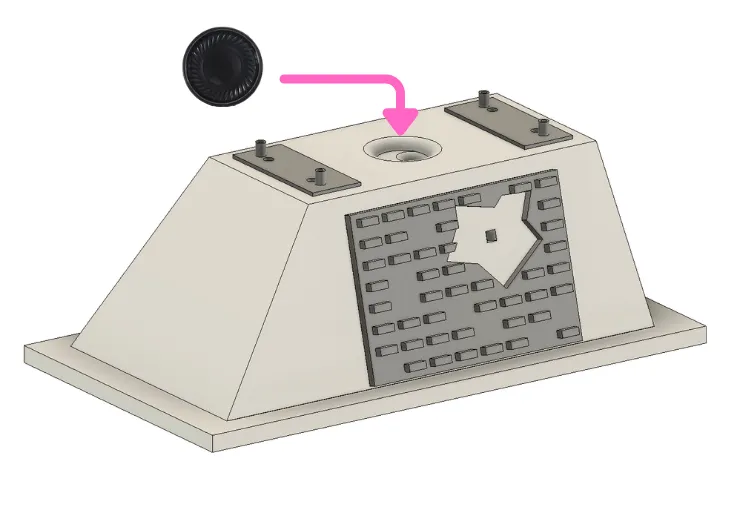
- Solder two long wires onto the 8 ohm speaker. Thread the wires through the hole in the top of the droid and hot glue the bottom of the speaker in place.
- Solder together the following components:
- Buck output+ to:
- UNO 5V
- DF Player Mini VCC
- Ultrasonic sensor VCC
- Buck output- to:
- UNO ground
- DF Player Mini ground
- Ultrasonic sensor ground
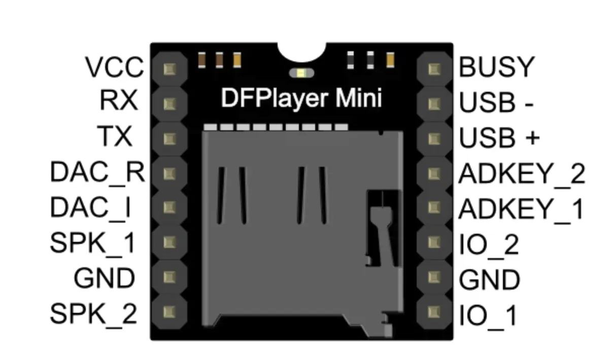
- DF player
- RX to UNO D11 through 1000 ohm resistor
- TX to UNO D12
- SPK_1 to speaker +
- SPK_2 to speaker -
- Ultrasonic sensor
- TRIG to D2
- ECHO to D3
Note: I recommend you use a screw shield for the UNO and a perfboard with female pin sockets for the DF Player to keep things organized. If using a perfboard, please be careful and safe by lifting it with nylon standoffs and covering the solder joints with Kapton tape.
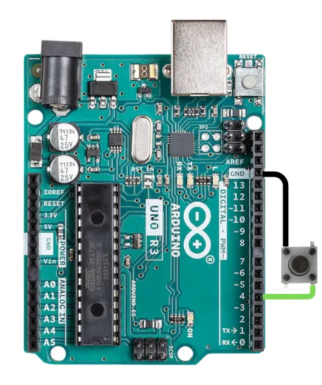
Button
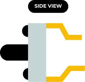
- Push the leads down and back so that they are sticking out straight behind the 6mm button.
- Solder two long wires onto the 6mm button switch on diagonal leads.
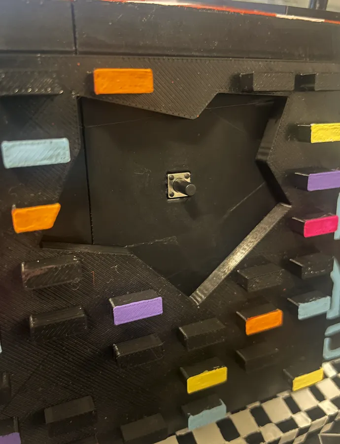
- Press it into the hole on the left side of the droid to keep it in place.
- Attach the wires to UNO GND and UNO D4, respectively.
- Add the 3D printed button cap to the top.
LEDs
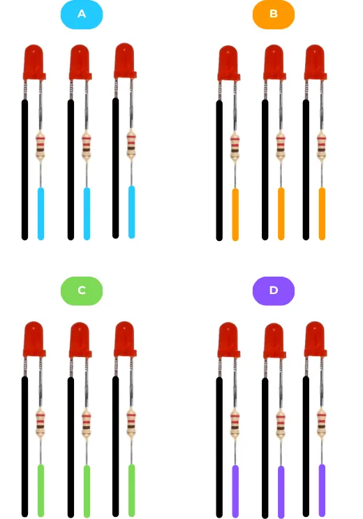
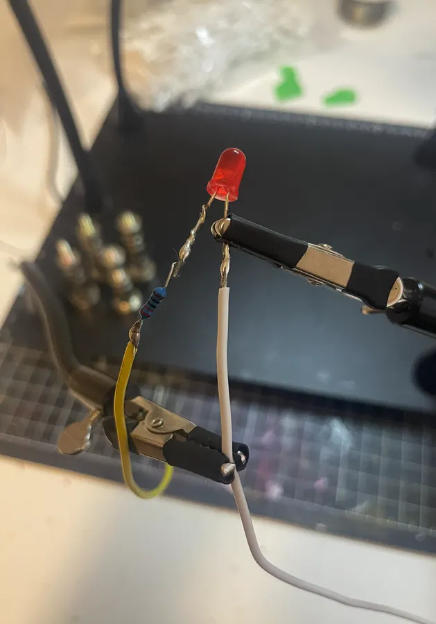
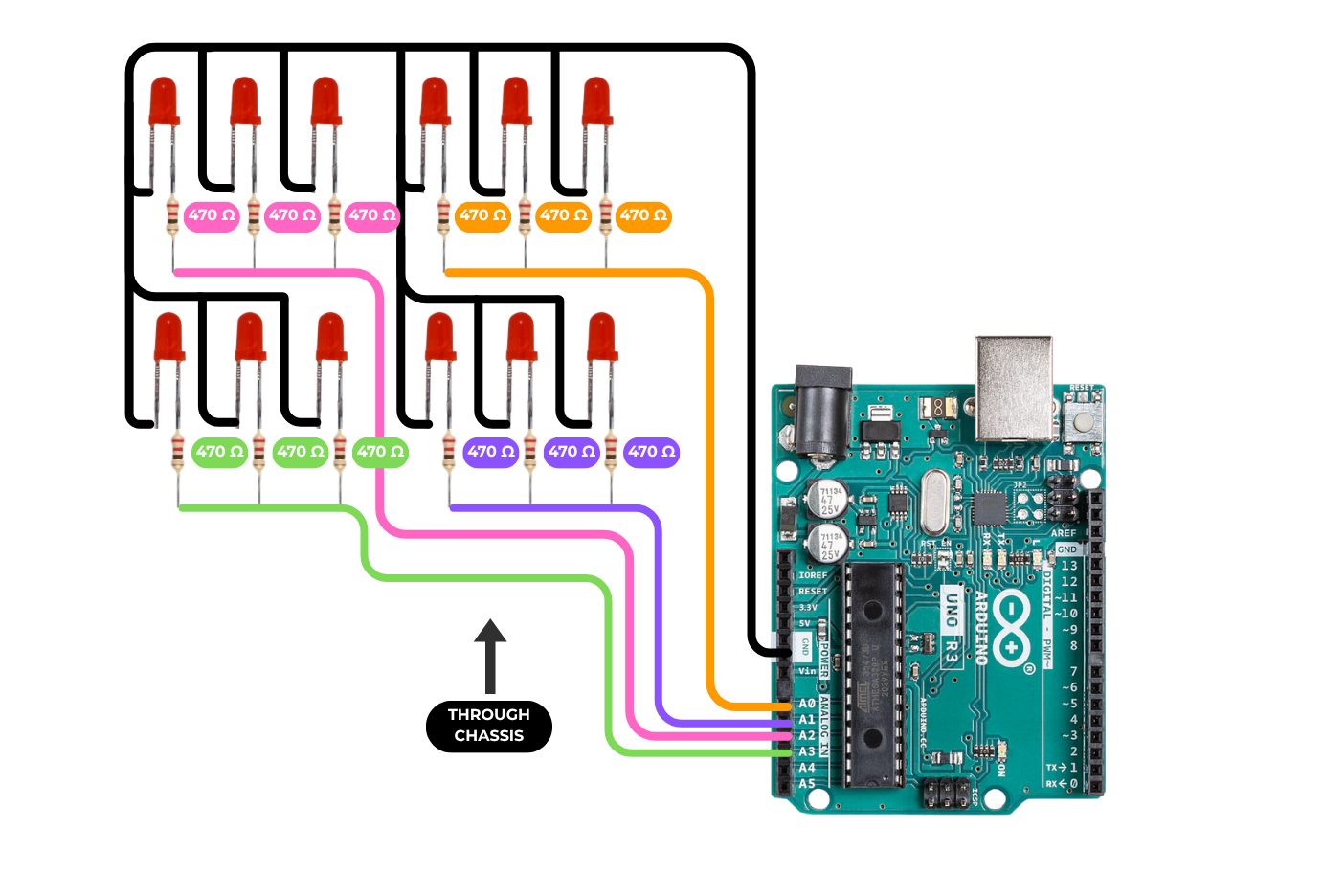
- Solder a 470 ohm resistor onto the positive leg of each of the 12 LEDs.
- Solder a wire (roughly 15 cm long) onto the ground leg of each LED. Use ONE colour of wire.
- Tip: solder close to the bulb or use heat shrink to insulate the negative legs from the positive legs, as they'll be in close proximity to each other.
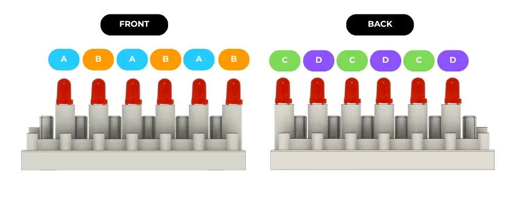
- Solder a wire (roughly 15 cm long) onto the positive leg of 3 of the LEDs. Use a single, new colour (Group A - blue here).
- Solder a wire (roughly 15 cm long) onto the positive leg of 3 of the LEDs. Use a single, new colour (Group B - orange here).
- Solder a wire (roughly 15 cm long) onto the positive leg of 3 of the LEDs. Use a single, new colour (Group C - green here).
- Solder a wire (roughly 15 cm long) onto the positive leg of the 3 remaining LEDs. Use a single, new colour (Group D - purple here).
LED Installation
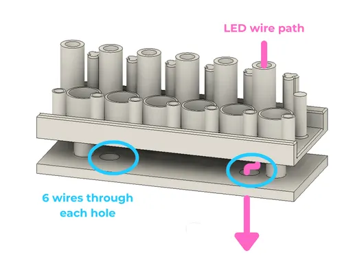
- Thread the LEDs into the "Top Greeblies - LEDs" in the pattern shown in the diagram.
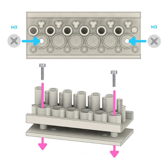
- Thread the wires through the top of the "Top Greeblies - base" as shown in the diagram.
- Use 4 18 mm M3 bolts to attach the "Top Greeblies - LEDs" to the bases.
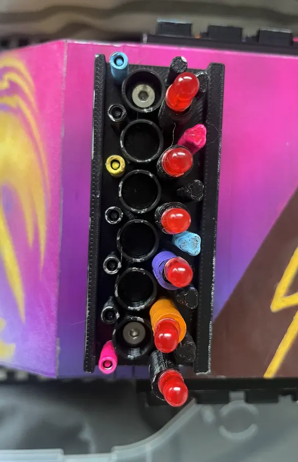
- Paint the exposed wire bundles black. (Or use heat shrink or electrical tape).
Soldering LED Groups
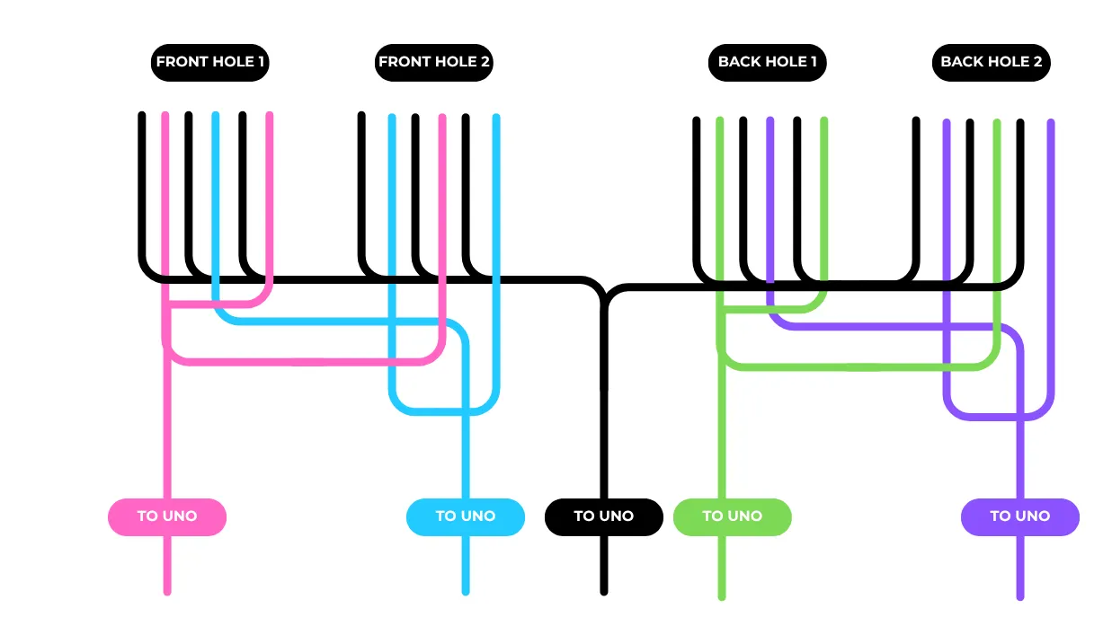
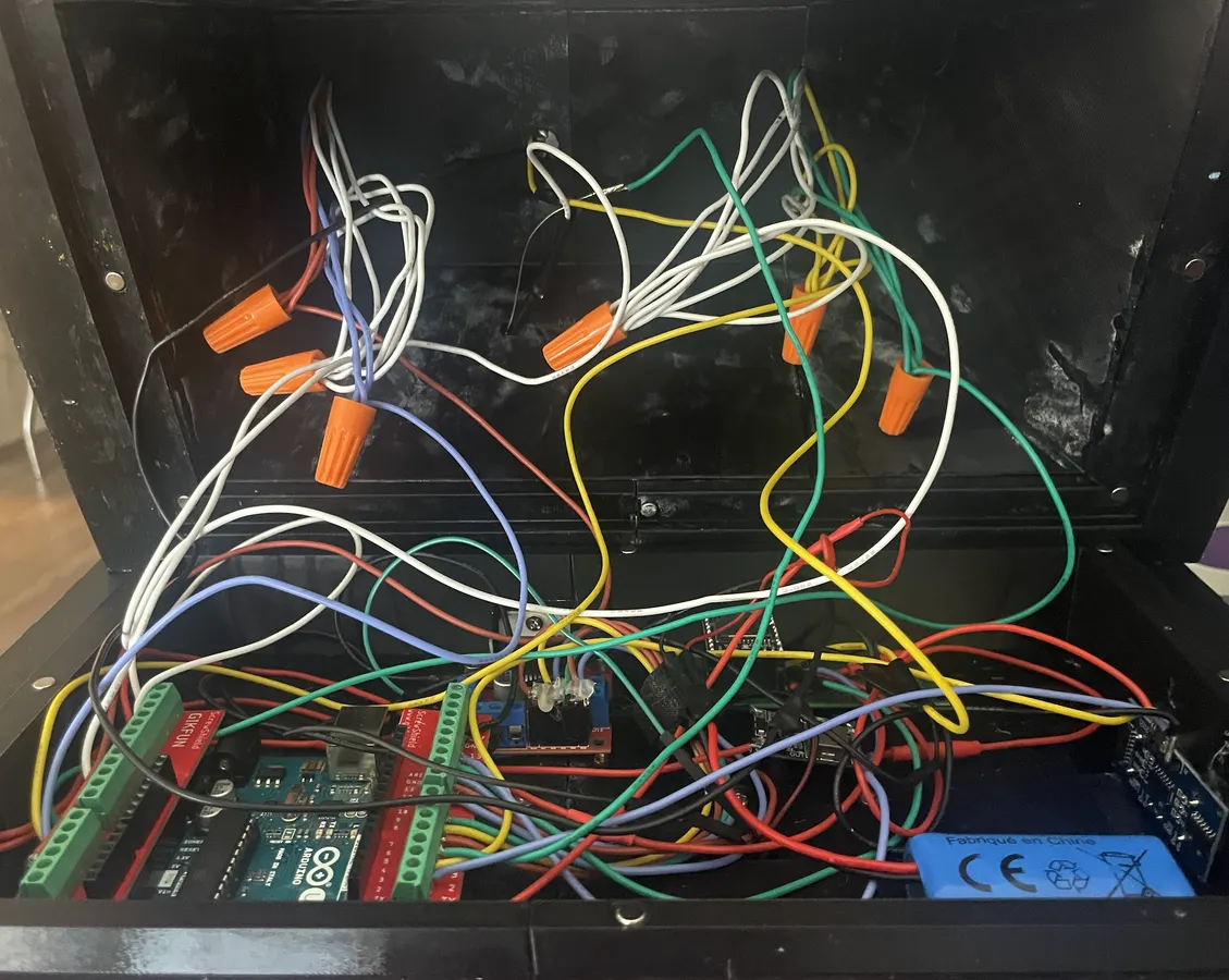
- Solder together all like colours INSIDE the droid (or use wire nuts). Have one "tail" wire come out of each bundle long enough to reach the UNO.
- Attach each group to the UNO.
- LED grounds (black) to UNO ground.
- Group A (blue) to UNO A0.
- Group B (orange) to UNO A1.
- Group C (green) to UNO A2.
- Group D (purple) to UNO A3.
Mount Electronics
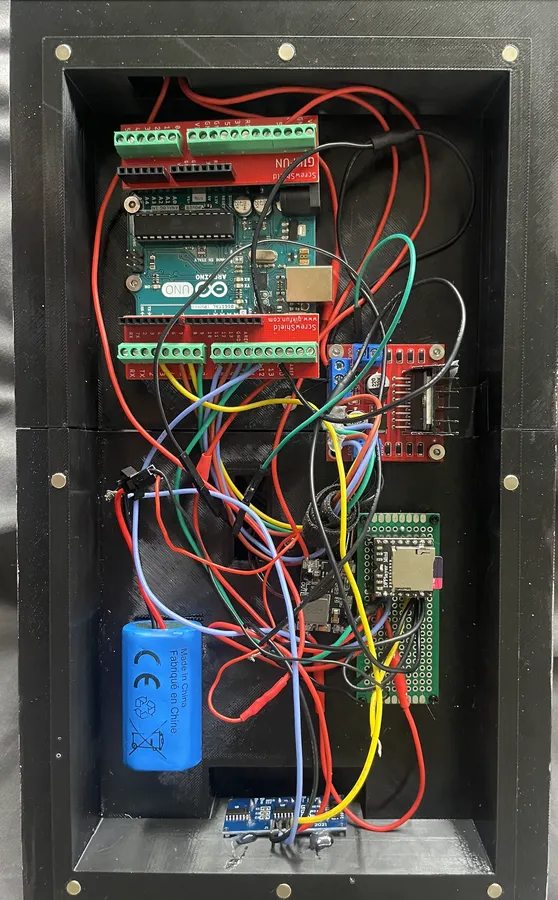
Mount your components to the bottom of the droid's insides.
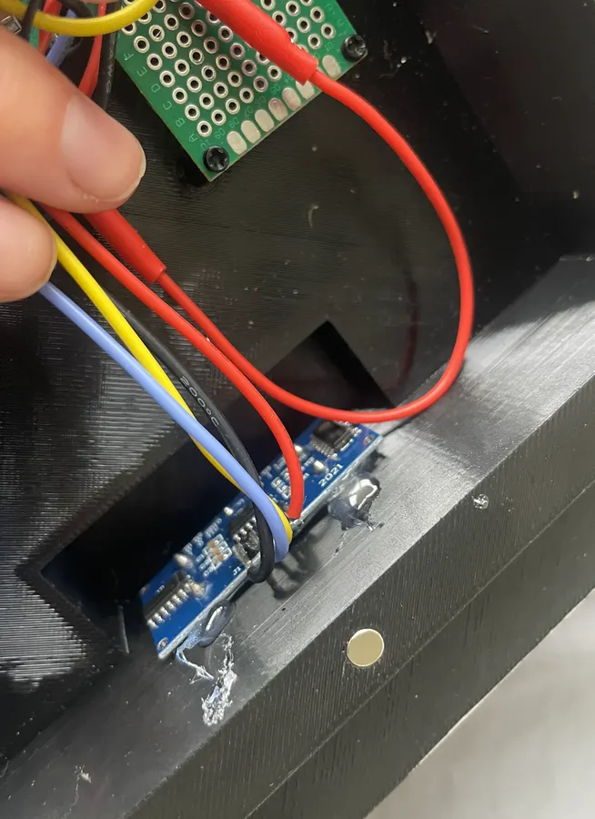
The ultrasonic sensor peeks out the two holes at the front of the chassis. Hold it in place with some hot glue.
If you're using heat-set inserts, this is the time to add them. If you're using the same arrangement as me, here's how I did mine.
Velcro the battery down so that it can be removed.
Check Your Work
Visually inspect and use a multimeter to check that all of your components are attached where they should be and that there are no shorts.
Here's the full diagram once again for your reference.
Let Him Loose!
Place the droid on the floor and flip the switch to ON. Watch it carefully to make sure the speed and obstacle detection are to your liking.
- You can edit the Arduino sketch to change the sensitivity and speed (see comments in sketch).
- If a wheel is moving in the wrong direction, take the motor's wires and swap their connections to the motor driver.
Next Steps / Areas for Improvement
If I do a v2, or if you make one and want some ideas to make it even better:
- Improving the amp/speaker will make the sound quality a lot better in party mode
- The caster is super loud, I'd replace it with something rubber if possible
- Use a motor driver that has less of a voltage drop to help with the torque issue OR try metal-geared motors instead
- The non-functional wheels / wheels with weird spacing drive me nuts, but unsure how to fix that. I think the back wheels would need to be able to swivel somehow
- I don't like the way the aluminum chassis sticks out the bottom. I'd definitely want to replace that with something else, maybe some extra long brackets for the motors?
- The CAD design I printed is too pointy. I've fixed that for the files you have access to, so if you make it, your droid will be filleted and look more like a real mouse droid than mine does
- Add heat-set M3 inserts to the top greeblies bases and to the wheel adapters so that the bolts don't have to tap themselves
Licenses
Arduino Code
The original Arduino code for this project is licensed under the MIT License.
You are free to use, copy, modify, and redistribute the code, including in other projects, provided that the original copyright and license notice are retained.
See LICENSE-MIT.txt in the files for the full license text.
3D Files
The original 3D-printable files are licensed under Creative Commons Attribution-NonCommercial 4.0 International (CC BY-NC 4.0).
You may copy, modify, remix, and share the files, provided that you:
- Give appropriate credit to Chaos Theory
- Link to the license
- Indicate if you made changes
- Do not use the files for commercial purposes
See LICENSE-CC.txt in the files for the full license text.
Star Wars Fan Project
This is an unofficial fan-made project. Star Wars, Mouse Droid, Sabine Wren, and related names, characters, designs, logos, and other intellectual property belong to their respective rights holders.
The licenses above apply only to my original contributions to this project and do not grant permission to use third-party intellectual property.
This project is not affiliated with or endorsed by Lucasfilm Ltd., The Walt Disney Company, or Disney.