Want to build a name tag that doesn't drain your battery and looks super cool at the same time? Meet the eInk Badge—a DIY electronic badge powered by the RP2040 and a crisp E Ink display. It shows your name, QR codes, or custom graphics and only uses power when the screen updates!
At the heart of the eInk Badge is the RP2040, a powerful and energy-efficient microcontroller developed by Raspberry Pi. Featuring a dual-core ARM Cortex-M0+ processor, it delivers solid performance for a wide range of embedded applications—from interactive wearables to responsive control systems.
Core highlights include:
- Dual-core ARM Cortex-M0+ running up to 133 MHz – enables multitasking and efficient code execution
- 264 KB of internal SRAM and support for external QSPI flash – plenty of memory for most projects
- Versatile I/O options – includes 2× UART, 2× SPI, 2× I²C, 16× PWM channels, 3× ADC inputs, and up to 30 GPIO pins
- Programmable I/O (PIO) – lets you create custom hardware interfaces in software
- USB 1.1 host/device support – native USB for data or programming
- Low-power 40 nm architecture – optimized for battery-powered and portable systems
- Drag-and-drop USB bootloader – makes flashing firmware simple and fast
- Broad language and ecosystem support – works with C/C++, MicroPython, CircuitPython, Rust, and others
Electronic Ink Display
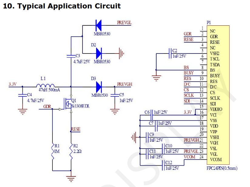
The eInk Badge uses the GDEY029F51 as its main display—a 2.9-inch E Ink module that supports four colors (black, white, red, and yellow) and has a resolution of 296×128 pixels. It’s controlled by the JD79661 driver IC and communicates via an SPI interface, making it straightforward to connect with microcontrollers such as the RP2040.
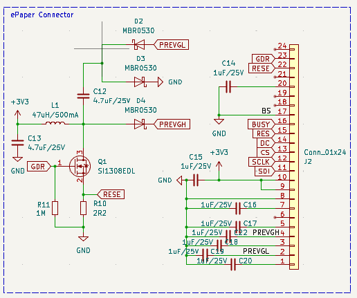
Its color support enables bold and readable visuals, even with minimal power usage—ideal for low-energy projects. For wiring and integration, the manufacturer provides a reference circuit in the official datasheet.
eInk Display suggested schematics
Schematics
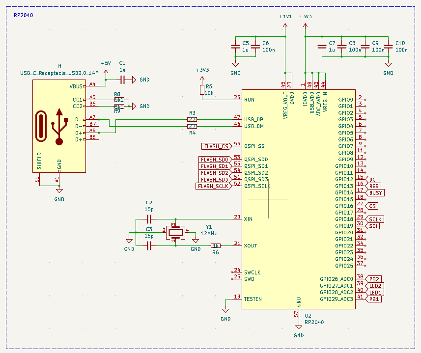
The brain of the badge is a RP2040. This microcontroller is programmed using an USB-C, in which only the USB2.0 pins are used.
The microcontroller also needs a 12MHz oscillator and a bunch of decoupling capacitors.
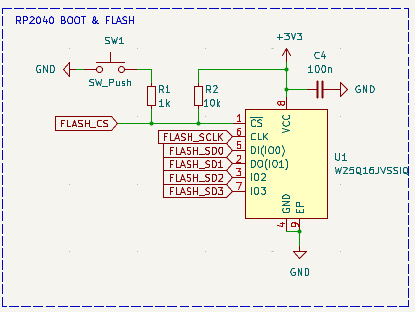
To store the program, the RP2040 uses an external FLASH memory. In this case we used the W25Q16, a 16Mbit memory with QSPI interface.
Here you will find the BOOT push button, which is used to reset the microcontroller and enable loading a new firmware version.
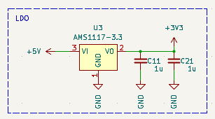
The board receives power through the 5V supplied by the USB port. A Low Dropout Regulator (LDO) then converts this to a 3.3V supply, which powers all the electronic circuits.
The display is connected to the board using a flat-cable connector. The circuit used is provided by the vendor.
Firmware
The firmware for the eInk Badge was developed using the Arduino IDE. To manage the E Ink display, we use the GxEPD2 library—a flexible Arduino library tailored for SPI-based e-paper screens. GxEPD2 supports a variety of e-paper panels from manufacturers like Waveshare and Good Display, and is optimized for efficient performance and low memory consumption on microcontrollers such as the RP2040, ESP32, and STM32.
This library offers a high-level interface for controlling e-paper displays, handling tasks like initialization, rendering, refreshing, and power management.
Build your own
The board is open source and the schematic and BOM are released yo sou can build your own eInk badge.
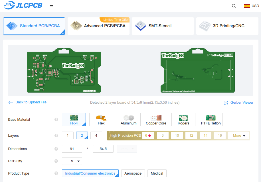
An excellent option to build your badge is JLCPCB. Here you can build your PCB. To do this you need to navigate to JLCPCB.com, and clink on Order now. Now you have to upload your gerber files.
Remember to change the Surface Finish to a LeadFree one in order to make your board ROHS compliant.
JLCPCB also offers PCB assembly (PCBA) services, which include populating and soldering components onto your board. To use this service, simply select the PCBA option and upload your Bill of Materials (BOM) file.
In a few days you will receive your board ready for use.