Build an automated, RFID-based toll gate system using Arduino, IR sensors, and a servo — perfect for makers, students, and IoT learners looking for a practical project.
Introduction
Automating everyday systems with microcontrollers is at the heart of the maker movement. In this project, we show how you can build a hands-free automatic toll gate system using an Arduino that detects vehicles, processes RFID-based payments, and opens a gate without manual intervention — ideal for makers, students, and hobbyists exploring embedded systems and IoT.
Project Overview
This system mimics real-world toll plazas by using simple electronic components and logical control with an Arduino Uno. When a vehicle arrives, an IR sensor detects its presence and prompts the system to read an RFID card. If the card’s balance is sufficient, the toll fee is deducted automatically, and a servo-controlled gate opens. A second IR sensor detects when the vehicle has passed, triggering the gate to close again.
Why This Project Matters
- Contactless Operation: Eliminates manual toll handling, enhances hygiene, and improves throughput speed.
- Beginner Friendly: Designed with approachable hardware and clear code logic.
- Scalable: Easily extendable with displays, IoT connectivity, cloud logging, and mobile interfaces.
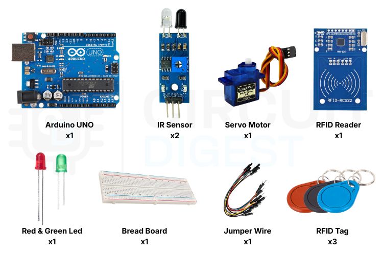
Components You’ll Need
Arduino Uno: The microcontroller that controls the entire system.
RFID Reader (RC522): Reads payment cards and sends UID to Arduino.
RFID Tags/Cards: Used to store balance and authorise access.
IR Sensor Modules (2): Detect vehicle arrival and exit.
Servo Motor: Acts as the gate barrier.
Red & Green LEDs: Show payment status (denied & approved).
Breadboard & WiresFor circuit prototyping.
How It Works — Step-by-Step
1. Detecting an Incoming Vehicle
The first IR sensor watches for a vehicle approaching the toll area. When a vehicle interrupts the IR beam, the system transitions into payment mode.
2. RFID Card Scan
Once the vehicle is in position, the driver taps their RFID card on the reader. The Arduino reads its unique ID and checks it against stored values.
3. Payment Validation
The system checks:
- If the card is recognised,
- If the balance is sufficient.
- If both checks pass, the toll amount is automatically deducted.
4. Gate Control
- Green LED lights up to indicate successful validation.
- The servo motor opens the gate to let the vehicle pass.
If validation fails (unknown card or insufficient balance), the red LED lights up, and the gate stays closed.
5. Reset for Next Vehicle
After the vehicle leaves, the second IR sensor triggers the gate to close and resets the system to await the next user.
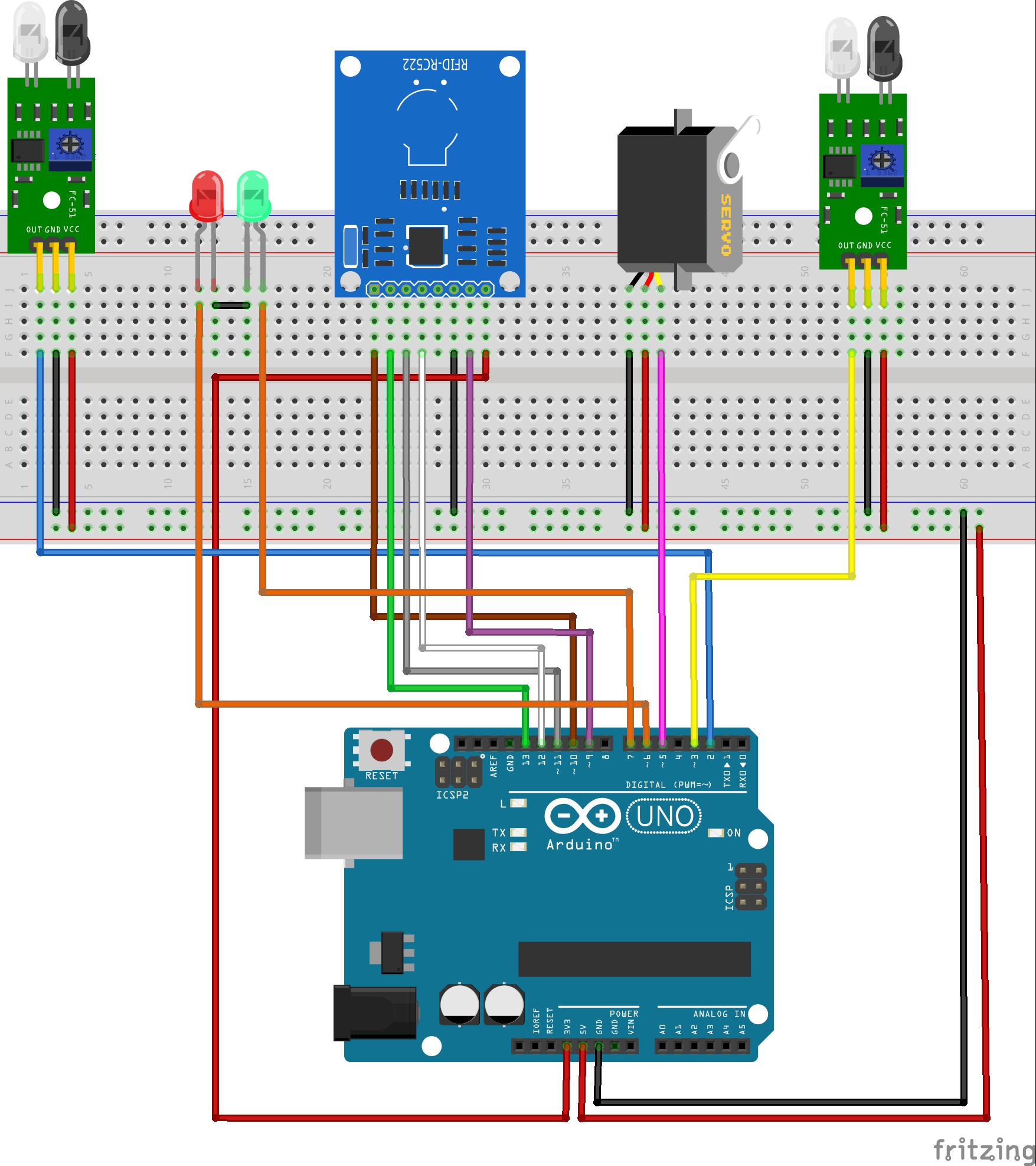
Circuit and Connections
You’ll wire each component to the Arduino as follows:
Basic Wiring Summary
- RFID Reader: Connect to SPI pins (SDA, SCK, MOSI, MISO) and 3.3V.
- IR Sensors: Digital input pins for entry & exit detection.
- Servo Motor: PWM-capable pin to drive the gate motion.
- LEDs: Output pins to show system status.
Arduino Code Logic
The sketch integrates:
- RFID communication using SPI
- Servo control for the gate
- Balance checks and LED feedback
- Sensor polling for vehicle detection
Code modularity makes it easy to modify features like variable toll rates or cloud logging.
Real-World Uses Beyond This Demo
This project is far from just a classroom demo. Variants of automated toll systems are used in:
- Highway toll plazas
- Parking facilities
- Gated communities
- Industrial vehicle entry systems
- Event access control points
Enhancements You Can Try
- Add an LCD or OLED display to show balance and status messages.
- Connect to Wi-Fi (ESP32) for cloud logging or real-time dashboards.
- Mobile interface to check balance remotely.
- SD card or database transaction logging.
Conclusion
This Automatic Toll Gate System Project Using Arduino combines simple sensors and RFID verification to simulate a full-featured, contactless toll solution that scales from hobby setups to advanced maker builds. Perfect for workshops, tech demos, and IoT portfolios, it highlights the spirit of innovation in the maker community.