Build a 6-DOF Arduino Robotic Arm From Scratch with 3D Printing, Web Dashboard Control, Detailed Wiring & Code — Perfect for Makers!
Robotic arms are captivating maker projects — combining mechanics, electronics, and embedded programming into one impressive build. Whether for education, experimentation, or automation, building your own Arduino robotic arm gives you hands-on experience with servo control, motion planning, and hardware design. This detailed guide takes you step-by-step through building a 6-Degree-of-Freedom (6-DOF) robotic arm using Arduino Uno, servo motors, 3D-printed parts and a slick web-based control dashboard.
Why This Project Matters
Robotic arms like this one are more than cool DIY gadgets. They mirror real industrial automation, capable of performing pick-and-place tasks, repetitive movements, and precise positioning. In professional settings, similar systems handle PCB assembly, laboratory material handling, and even surgical assistance — all thanks to precise motion control and programmable behavior.
By building this project, makers learn:
- Servo motor control using Arduino PWM
- Web Serial communication for live control
- 3D design and mechanical assembly
- Embedded programming with real-time response
This makes the project ideal for hobbyists, students, and aspiring roboticists alike.
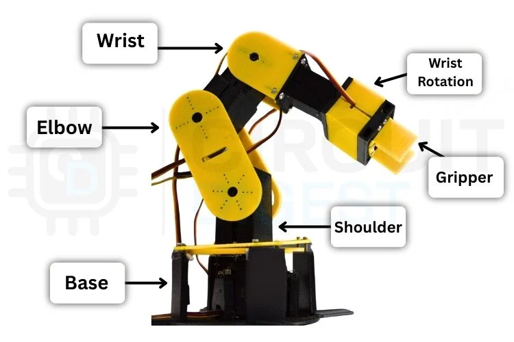
Understanding Robotic Motion & Mechanics
Before you start assembling, it helps to grasp a few key concepts:
Degrees of Freedom (DOF)
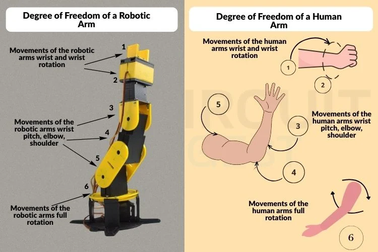
This refers to how many independent movements the arm can make. A 6-DOF arm — like ours — offers highly flexible motion, closer to human reach and rotation than simpler arms.
Servo Motors
Servos receive PWM signals from the Arduino, turning those signals into controlled joint angles. Most hobby servos operate between 0° and 180°, allowing precise positioning for each joint.
Power Considerations
Unlike LEDs or simple sensors, servos are power hungry. An external power supply (e.g., 5 V, 2 A) is essential to drive the motors reliably without browning out the Arduino.
Degree of Freedom Comparison
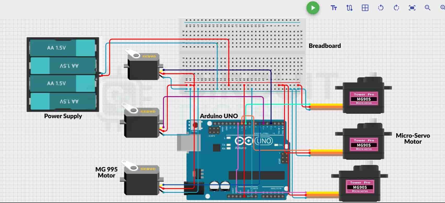
Circuit Design & Wiring Guide
Your Arduino Uno sits at the core of the system. Each servo’s control line connects to a PWM-capable pin on the Arduino, while their power and ground lines connect to a common external supply. Be sure to share a common ground between the Arduino and servo power supply so signals remain synchronized.
A breadboard helps keep wiring clean and organized, allowing you to distribute power safely to all six servos.
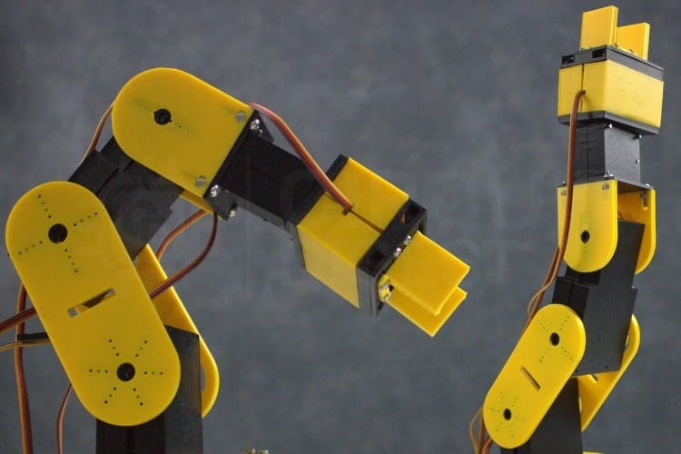
Mechanical Assembly and 3D Printing
Most structural parts of the arm — including the base, links, and gripper housing — are 3D printed. Use CAD tools like Fusion 360 or SolidWorks to design or customize parts. After printing, inspect for fitting accuracy, mount each servo into its slot, and assemble using screws and nuts.
Tip: Print moving parts and structural parts in different colors (e.g., yellow for moving, black for base) to visually distinguish mechanisms.
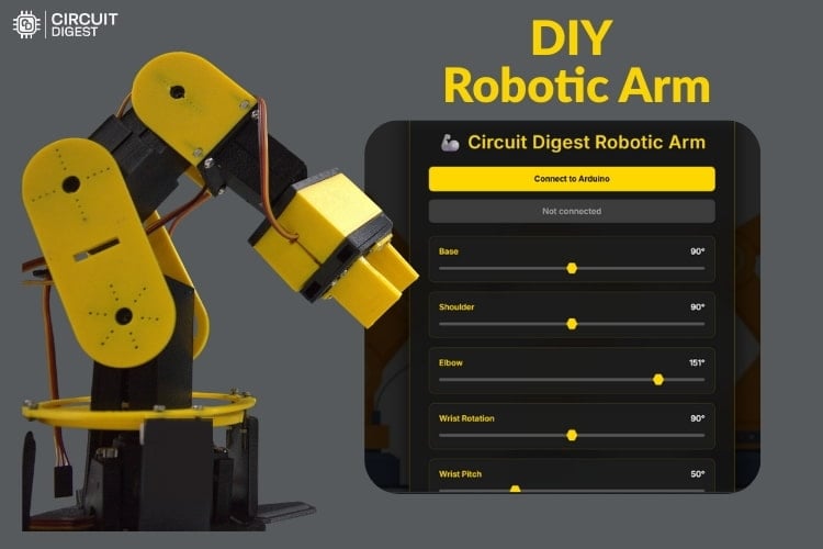
Code & Web Dashboard Control
The Arduino code initializes all servos and waits for commands via the Web Serial API, enabling real-time control from a browser. Each slider on the dashboard corresponds to a joint’s angle, offering intuitive manual control. You can also record sequences, save motion files (JSON), and replay actions — turning your arm into a programmable robot.
Here’s a snippet showing how the code initializes servos:
#include <Servo.h>

Servo base, shoulder, elbow, wristRot, wristPitch, gripper;

int BASE_INIT = 90;
int SHOULDER_INIT = 90;
// … (initial positions for all servos)
This places all servos in a neutral starting position before you begin controlling them via dashboard.
Operating Your Robotic Arm
Once assembled and connected:
- Upload the Arduino sketch.
- Ensure all servos are centered at 90° before assembling servo horns — this prevents binding.
- Open the web dashboard in a Chromium-based browser (for Web Serial API support).
- Select the correct COM port and start moving sliders to control the arm.
Common troubleshooting includes ensuring the correct COM port, matching the baud rate, and proper servo alignment.
Expand Beyond the Basics
Once you master this build, you can extend it by:
- Adding wireless control
- Integrating vision systems
- Exploring AI/ML motion planning
- Adding IoT connectivity
Final Thoughts
This Arduino robotic arm project isn’t just about making something cool — it’s about learning key robotics concepts, refining your hardware-building skills, and creating a foundation for future automation projects. With its 6 DOF, web dashboard control, and custom 3D parts, this build is a fun and powerful step into practical robotics. You can find Arduino project ideas for all skill levels to fuel your next maker creation.