Project adjusted to be used in a Christmas Village with LED lights. No relay's needed. Small adjustment in code.
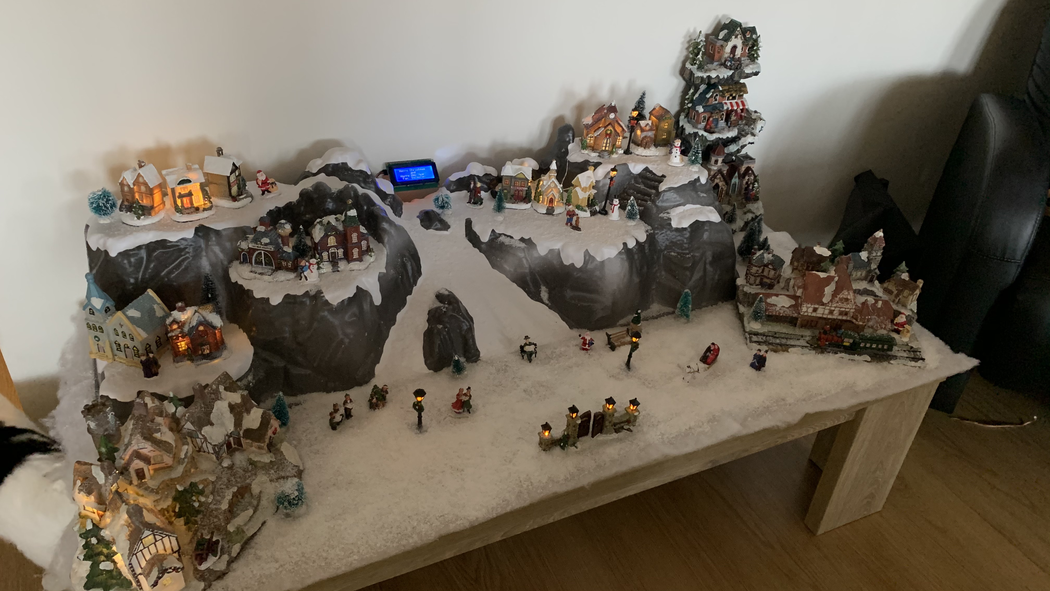
This project shows you how you can automate the lights of your Christmas Village. On the photo there is also an LCD 20x4 display, but is not going to be used in this project.
I saw the original project last year and always had in mind to build it myself. Since I live in an apartment in the Netherlands, it is not possible to use outside decoration. So what we do, is setup a Christmas village. But, like all other Christmas villages, the lights are all on or off.... It is not realistic.
My idea was to use the Arduino to control the lights in the village, but also Chrismas Lights flashing to the music. So I took the original idea and adjusted it, so I can use it in the village.
Without the music, I programmed it with a randomizer. To let it work with music, it uses MIDI.
How Does It Work?
Controlling Lights in Sync With a Song
From the original project: Above is a screenshot of Studio One DAW software (digital audio workstation software) that I used for this project. The MIDI track in the DAW software is in sync with a song. I turned the notes from C3 to E6 (excluding sharp notes) on and off in the MIDI track to control the lights. I used Hairless MIDI to serial bridge (Mac users: there is a 64bit version, but not stable when using Big Sur) to send the MIDI signals to the Arduino and programmed it to turn specific relays on and off according to the notes received. Now the DAW software controls the lights according to the song’s rhythm.
I did not use sharp notes (the black keys) because, if you have a real MIDI keyboard, you can program the lights with it. You can play a Glissando and control all the lights!
The leds are connected to the tree 74HC595 with a resistor of 150 ohm between the ic output and the leds. Three bytes are used to store the light states in the program (on/off). The music software sends out the MIDI data, which is received by the Arduino and sets the corresponding bit of one of the three bytes to 0 or 1. The three bytes are shifted out of the registers and then are latched on so the leds turn on/off. After all the bytes are sent and the process is finished, they are latched, which prevents the leds from turning on/off while shifting the data. Now get ready to build your own Christmas light show with Arduino!
Building the Circuit for Our Christmas Light Show With Arduino
Set up the circuit as shown in the diagram.
Setting Up the Software
- Install Studio One (or any DAW software). I used Studio One 5 Free! Most of the features work in the free version.
- Install loopMIDI for creating a virtual MIDI port (windows).
- Create a virtual MIDI Port on Mac OS (using Audio/MIDI Configuration)
- Set up the loopMIDI/virtual MIDI port as a new instrument in the DAW software.
Windows Studio One 5:
- Press Ctrl+,
- Go to ‘External Devices’
- Add
- New Instrument
- Give it a useful Device Name like "Virtual Instrument"
- Send to: loopMIDI port
- OK
- OK
Mac OS Studio One 5:
- cmd+,
- Go to ‘External Devices’
- Add
- New Instrument
- Give it a useful Device Name like "Virtual Instrument"
- Send to: IAC Virtual MIDI Cable
- OK
- OK
Open this file for the song "Carol of the Bells", click the area shown below and select Virtual Instrument
If you are not using Studio One, you can start a new song, create a MIDI track, and send its output to the newly created instrument.
Upload the Christmas Light Show Code to Your Arduino
Download the Christmas light show code, or copy and paste it from below.
/* Christmas New year light show with Arduino
*  by Akshay James
*  My blog: techmusician.wordpress.com/2017/01/01/the-arduino-lights-project/
*
* This project was inspired from a YouTube video by John Storms
* from his channel ListenToOurLights (http://www.youtube.com/user/listentoourlights).
* Thank you.

* GND (pin 8) to ground,
* Vcc (pin 16) to 5V
* OE (pin 13) to ground
* MR (pin 10) to 5V
*
* DS (pin 14) to Ardunio DigitalPin 9 (blue wire)
* SH_CP (pin 11) to to Ardunio DigitalPin 8 (yellow wire)
* ST_CP (pin 12) to Ardunio DigitalPin 10 (green wire)
*/

#include"notes_bits.h"

//Pin connected to latch pin (ST_CP) of 74HC595
const int latchPin = 9;
//Pin connected to clock pin (SH_CP) of 74HC595
const int clockPin = 8;
//Pin connected to Data in (DS) of 74HC595
const int dataPin = 10;

int pitch, cmd, velocity;
int light;
boolean state;

byte lightData1 = 0, lightData2 = 0, lightData3 = 0; //

void setup() {
pinMode(latchPin, OUTPUT);
pinMode(dataPin, OUTPUT);
pinMode(clockPin, OUTPUT);
Serial.begin(38400);

}

void loop() {

//read the midi signal
if(Serial.available()>2) {
cmd = Serial.read();
pitch = Serial.read();
velocity = Serial.read();

//the lights are set according to the data on MIDI ch.1
if(cmd==144) state=1;               //144 ch1 noteON ; No relay used!
else if(cmd==128) state=0;        //128 ch1 noteOFF  ; No relay used!

// so that lights don't change while the new data is being shifted
digitalWrite(latchPin, LOW);

light = getBit(pitch);
// set the corresponding bit in lightData
if(light<8)
bitWrite(lightData1, light, state);
else if(light<16){
light-=8;
bitWrite(lightData2, light, state);
}
else {
light-=16;
bitWrite(lightData3, light, state);
}

// shift out the data
shiftOut(dataPin, clockPin, MSBFIRST, lightData3);
shiftOut(dataPin, clockPin, MSBFIRST, lightData2);
shiftOut(dataPin, clockPin, MSBFIRST, lightData1);

// turn on the lights according to the new data
digitalWrite(latchPin, HIGH);

}
}
Also, make a notes_bits.h file. Copy and paste the code below to it or download it from here.
/*Which bit has to be turned ON or OFF is found
* with the below function.
*
* The range of music notes used for the control
* of lights is from C3 to E6.
* (sharp notes are excluded)     (total 24 lights)
*
* So, this function will return the number of the bit
* to be set.
* For eg, C3(note 62) corresponds to the first light,
* So this function will return '1'.
*
* Similarly, '2' is returned for D3(note 64), etc.
*
*/

int getBit(int p) {
switch(p) {
case 60: return 0; //note C3 (middle C)
case 62: return 1; //D3
case 64: return 2; //E3
case 65: return 3; //F3
case 67: return 4; //G3
case 69: return 5; //A3
case 71: return 6; //B3
case 72: return 7; //C4
case 74: return 8; //D4
case 76: return 9; //E4
case 77: return 10; //F4
case 79: return 11; //G4
case 81: return 12; //A4
case 83: return 13; //B4
case 84: return 14; //C5
case 86: return 15; //D5
case 88: return 16; //E5
case 89: return 17; //F5
case 91: return 18; //G5
case 93: return 19; //A5
case 95: return 20; //B5
case 96: return 21; //C6
case 98: return 22; //D6
case 100: return 23; //E6
}
}
Setting the Baud Rate
Connect the Arduino to your computer. Then open Hairless Serial to MIDI bridge and select the Arduino port as the serial port and MIDI in port as loopMIDI / Virtual Midi.
Then, go to File > Preferences > Set the Baud rate to 38400 > OK.
We have to change the baud rate because we need it to be higher than the MIDI’s baud rate, which is 31250. If the baud rate is below that, we will have a noticeable delay in the lights.
Then tick the Serial<->MIDI bridge option.
To start the lights:
Go back to Studio One and play the song. You should see the Green LED in Hairless Serial to MIDI bridge blinking. If that is there, then the led's should work.
Below is the village. Please ignore the lcd-display. It is not in this project, just something extra...
As said before, I also created a script to look like the village is alive, when I don't have the laptop connected to Arduino. So if you want to do that, please upload the following code to your Arduino
/* Christmas Village random lights with Arduino
   by André Dalmolen


  This project was inspired from a YouTube video by John Storms
  from his channel ListenToOurLights (http://www.youtube.com/user/listentoourlights).
  And the Christmas Light Show with Arduino by Akshay James
  Thank you.

  GND (pin 8) to ground,
  Vcc (pin 16) to 5V
  OE (pin 13) to ground
  MR (pin 10) to 5V

  DS (pin 14) to Ardunio DigitalPin 9 (blue wire)
  SH_CP (pin 11) to to Ardunio DigitalPin 8 (yellow wire)
  ST_CP (pin 12) to Ardunio DigitalPin 10 (green wire)
*/

//Pin connected to latch pin (ST_CP) of 74HC595
const int latchPin = 9;
//Pin connected to clock pin (SH_CP) of 74HC595
const int clockPin = 8;
//Pin connected to Data in (DS) of 74HC595
const int dataPin = 10;

byte leds = 0;    // Variable to hold the pattern of which LEDs are currently turned on or off

int pitch, cmd, velocity;
int light;
boolean state;

byte lightData1 = 0, lightData2 = 0, lightData3 = 0; //

void setup() {
  pinMode(latchPin, OUTPUT);
  pinMode(dataPin, OUTPUT);
  pinMode(clockPin, OUTPUT);
  Serial.begin(9600);
  // Init turn all lights on!
  state=1;
  for (int j = 0; j<24; j++){
    digitalWrite(latchPin, LOW);
    if (j < 8) {
      light = j;
      bitWrite(lightData1, light, state);
    } else if (j < 16) {
      light = j - 8;
      bitWrite(lightData2, light, state);
    }
    else {
      light = j - 16;
      bitWrite(lightData3, light, state);
    }
    shiftOut(dataPin, clockPin, LSBFIRST, lightData3);
    shiftOut(dataPin, clockPin, LSBFIRST, lightData2);
    shiftOut(dataPin, clockPin, LSBFIRST, lightData1);

    // turn on the lights according to the new data
    digitalWrite(latchPin, HIGH);
    delay(500);
  }

}

void loop() {
    // State of light randomizer.
    state = random(0, 2);
    // Led randomizer.
    int i = random(0, 24);
    //Serial.println("State : " +String(state));
    //Serial.println("Led : " + String(i));

    // so that lights don't change while the new data is being shifted
    digitalWrite(latchPin, LOW);

    // set the corresponding led in lightData
    if (i < 8) { //First IC
      light = i;
      bitWrite(lightData1, light, state);
    } else if (i < 16) { Second IC
      light = i - 8;
      bitWrite(lightData2, light, state);
    }
    else { //Third IC
      light = i - 16;
      bitWrite(lightData3, light, state);
    }

    // shift out the data
    shiftOut(dataPin, clockPin, LSBFIRST, lightData3);
    shiftOut(dataPin, clockPin, LSBFIRST, lightData2);
    shiftOut(dataPin, clockPin, LSBFIRST, lightData1);

    // turn on the lights according to the new data
    digitalWrite(latchPin, HIGH);
    delay(10000); //Change every 10 seconds
}
This project was inspired from a YouTube video by John Storm from his channel ListenToOurLights (http://www.youtube.com/user/listentoourlights). And the Christmas Light Show with Arduino by Akshay James where I made this FORK from.
Thank you.