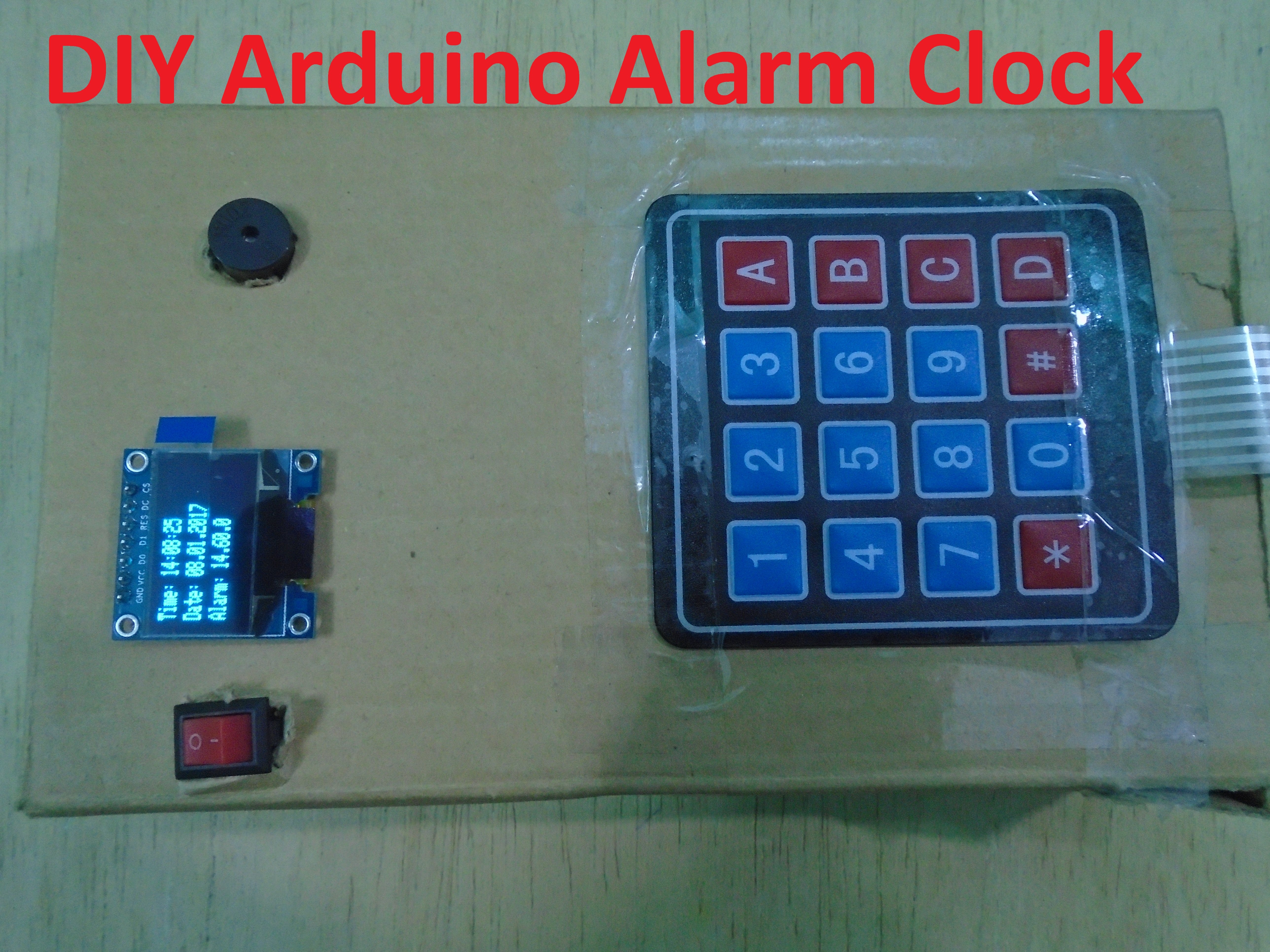
Learn how to make a DIY Arduino Alarm Clock Device using RTC DS3231 module.
In this article, we are going to make a DIY Arduino Alarm Clock Device in which we will use the RTC DS3231 module to get the current time and date and the OLED will show this time and date. We will use the EEPROM library to store the alarm time which we will enter using the 4X4 keypad module.
When the new alarm time we entered will match with the current alarm time, then the buzzer will start to beep until we hold the ‘C’ key on the keypad. The ‘#’ key will be used to change the password.
Required Components For DIY Arduino Alarm Clock Device
The required components for DIY Arduino Alarm Clock Device are as follows
- Arduino Uno
- 128X32 Monochrome OLED
- RTC DS3231 module
- 4X4 keypad
- 9V battery
- Buzzer
- Switch
- Connecting wires
Circuit Diagram
The circuit diagram for DIY Arduino Alarm Clock Device is a little bigger one. First of all, connect the OLED with the Arduino. The connections for the OLED with the Arduino are as follows
- CS pin of OLED to pin 10 of Arduino
- DC pin of OLED to pin 9 of Arduino
- RST pin of OLED to pin 8 of Arduino
- D1 or CLK pin of OLED to pin 11 of Arduino
- D0 or DIN pin of OLED to pin 13 of Arduino
To read more about Arduino OLED interfacing, follow this | Arduino OLED Tutorial
Then connect the DS3231 module with the Arduino. Connections are as follows
- Connect the GND of DS3231 to the GND of Arduino.
- Connect the VCC of DS3231 to the 5V of Arduino.
- Connect the SDA of DS3231 to the A4 of Arduino.
- Connect the SCL of DS3231 to the A5 of Arduino.
To read more about Arduino DS3231 interfacing, follow this | Arduino Real time clock (RTC) and Temperature Monitor using DS3231 module
After that, connect the 4X4 keypad with the Arduino. Connect the first 4 pins of keypad which are rows to the A0, A1, A2, A3 and the last four which are to the column pins to the 6, 5, 4, and 3.
Connect the positive pin of buzzer to the pin 7 of Arduino and the negative of buzzer to the GND of Arduino.
In the end, connect the positive wire of battery to one end of switch and the other end of switch to the Vin of Arduino. Then connect the negative wire of battery to the GND of Arduino
Code Explanation
Firstly, we included the libraries for the keypad, DS3231 RTC and OLED. The EEPROM library we included will help us in storing the Alarm time. The OLED works with Arduino through the SPI communication, so we included the SPI library. Similarly we included the ‘Wire’ library for the DS3231 because DS3231 works with Arduino through the I2C communication and the ‘Wire’ library is for the I2C communication.
#include <EEPROM.h>
#include <Keypad.h>
#include <DS3231.h>
#include <SPI.h>
#include <Wire.h>
#include <Adafruit_GFX.h>
#include <Adafruit_SSD1306.h>
In the below part of code, we defined the pins for the DS3231, buzzer and OLED. Then we initialized some variables which will help us in storing some data. After that, we defined the pins for the 4X4 keypad.
DS3231 rtc(SDA, SCL);
Time t;
#define buz 7
#define OLED_MOSI 11
#define OLED_CLK 13
#define OLED_DC 9
#define OLED_CS 10
#define OLED_RESET 8
Adafruit_SSD1306 display(OLED_MOSI, OLED_CLK, OLED_DC, OLED_RESET, OLED_CS);
int Hor, Min, Sec, tim, dat, h, m, s;
int ASCII = 48;
char key = 0;
char buffer[2];
const byte numRows= 4;
const byte numCols= 4;
char keymap[numRows][numCols]=
{
{'1', '2', '3', 'A'},
{'4', '5', '6', 'B'},
{'7', '8', '9', 'C'},
{'*', '0', '#', 'D'}
};
byte rowPins[numRows] = {A0, A1, A2, A3};
byte colPins[numCols]= {6, 5, 4, 3};
Keypad myKeypad= Keypad(makeKeymap(keymap), rowPins, colPins, numRows, numCols);
In the setup function, we started the ‘wire’ and ‘rtc’ communication. Then we declared the buzzer pin as output pin and called the ‘welcome’ function which will print the ‘Welcome to electronicshobbyists’ on the OLED.
Wire.begin();
rtc.begin();
pinMode(buz, OUTPUT);
display.begin(SSD1306_SWITCHCAPVCC);
display.clearDisplay();
display.setTextColor(WHITE);
display.setTextSize(1);
welcome();
In the loop function, we get the time and date from the RTC DS3231 module and stored it in the variables. Then we looked for if any key is pressed or not. If ‘C’ is pressed, then it will stop the buzzer and will change the minutes to 60 which will stop it from alarming next day. If ‘#’ is pressed, then it will ask you for new alarm time.
t = rtc.getTime();
Hor = t.hour;
Min = t.min;
Sec = t.sec;
tim = rtc.getTimeStr();
dat = rtc.getDateStr();
char key = myKeypad.getKey();
if (key == 'C'){
digitalWrite(buz, LOW);
EEPROM.write(2, ASCII+6);
EEPROM.write(3, ASCII);
}
if(key == '#'){
display.clearDisplay();
display.setCursor(0,0);
display.print("Enter New Time");
display.setCursor(0,10);
display.display();
int j =0;
int i=0;
while( j<6)
{
if(i==2 || i == 5){
display.print(":");
display.display();
i++;
}

key=myKeypad.getKey();
if(key)
{
display.print(key);
display.display();
EEPROM.write(j,key);
j++;
i++;
}
}
}
In the below function, it will compare the current time with the alarm time and if the time will match, then the buzzer will start to beep.
void checkalarm(){
if( Hor == h && Min == m)
{
delay(200);
display.clearDisplay();
display.setCursor(0,10);
display.print("Hold C to stop Alarm");
display.display();
digitalWrite(buz, HIGH);
delay(200);
}
}
The below function will store the alarm time you entered in the variable so that we can compare it with the current time.
void changealarm(){
buffer[0]=EEPROM.read(0);
buffer[1]=EEPROM.read(1);
h = atoi(buffer);
buffer[0]=EEPROM.read(2);
buffer[1]=EEPROM.read(3);
m = atoi(buffer);
buffer[0]=EEPROM.read(4);
buffer[1]=EEPROM.read(5);
s = atoi(buffer);
}
The below function will print the current time, current date and the alarm time on the OLED.
void timedate(){
display.clearDisplay();
display.setTextColor(WHITE);
display.setTextSize(1);
display.setCursor(0,0);
display.print("Time: ");
display.print(rtc.getTimeStr());
display.setCursor(0,10);
display.print("Date: ");
display.print(rtc.getDateStr());
display.setCursor(0,20);
display.print("Alarm: ");
display.print(h);
display.print(".");
display.print(m);
display.print(".");
display.print(s);
display.display();
}
Code
#include <EEPROM.h>

#include <Keypad.h>

#include <DS3231.h>

#include <SPI.h>

#include <Wire.h>

#include <Adafruit_GFX.h>

#include <Adafruit_SSD1306.h>

DS3231 rtc(SDA, SCL);

Time t;

#define buz 7

#define OLED_MOSI 11

#define OLED_CLK 13

#define OLED_DC 9

#define OLED_CS 10

#define OLED_RESET 8

Adafruit_SSD1306 display(OLED_MOSI, OLED_CLK, OLED_DC, OLED_RESET, OLED_CS);

int Hor, Min, Sec, tim, dat, h, m, s;

int ASCII = 48;

char key = 0;

char buffer[2];

const byte numRows= 4;

const byte numCols= 4;

char keymap[numRows][numCols]=

{

{'1', '2', '3', 'A'},

{'4', '5', '6', 'B'},

{'7', '8', '9', 'C'},

{'*', '0', '#', 'D'}

};

byte rowPins[numRows] = {A0, A1, A2, A3};

byte colPins[numCols]= {6, 5, 4, 3};

Keypad myKeypad= Keypad(makeKeymap(keymap), rowPins, colPins, numRows, numCols);

void setup() {

Wire.begin();

rtc.begin();

pinMode(buz, OUTPUT);

display.begin(SSD1306_SWITCHCAPVCC);

display.clearDisplay();

display.setTextColor(WHITE);

display.setTextSize(1);

welcome();

//uncomment these lines to set the date and time

//rtc.setDOW(SATURDAY); // Set Day-of-Week to SUNDAY

//rtc.setTime(10, 54, 0); // Set the time to 12:00:00 (24hr format)

//rtc.setDate(7, 1, 2017); // Day, Month, Year

}

void loop() {

t = rtc.getTime();

Hor = t.hour;

Min = t.min;

Sec = t.sec;

tim = rtc.getTimeStr();

dat = rtc.getDateStr();

char key = myKeypad.getKey();

if (key == 'C'){

digitalWrite(buz, LOW);

EEPROM.write(2, ASCII+6);

EEPROM.write(3, ASCII);

}

if(key == '#'){

display.clearDisplay();

display.setCursor(0,0);

display.print("Enter New Time");

display.setCursor(0,10);

display.display();

int j =0;

int i=0;

while( j<6)

{

if(i==2 || i == 5){

display.print(":");

display.display();

i++;

}

key=myKeypad.getKey();

if(key)

{

display.print(key);

display.display();

EEPROM.write(j,key);

j++;

i++;

}

}

}

changealarm();

checkalarm();

timedate();

}

void checkalarm(){

if( Hor == h && Min == m)

{

delay(200);

display.clearDisplay();

display.setCursor(0,10);

display.print("Hold C to stop Alarm");

display.display();

digitalWrite(buz, HIGH);

delay(200);

}

}

void changealarm(){

buffer[0]=EEPROM.read(0);

buffer[1]=EEPROM.read(1);

h = atoi(buffer);

buffer[0]=EEPROM.read(2);

buffer[1]=EEPROM.read(3);

m = atoi(buffer);

buffer[0]=EEPROM.read(4);

buffer[1]=EEPROM.read(5);

s = atoi(buffer);

}

void timedate(){

display.clearDisplay();

display.setTextColor(WHITE);

display.setTextSize(1);

display.setCursor(0,0);

display.print("Time: ");

display.print(rtc.getTimeStr());

display.setCursor(0,10);

display.print("Date: ");

display.print(rtc.getDateStr());

display.setCursor(0,20);

display.print("Alarm: ");

display.print(h);

display.print(".");

display.print(m);

display.print(".");

display.print(s);

display.display();

}

void welcome(){

display.setCursor(0,0);

display.print(" Welcome ");

display.display();

display.setCursor(0,10);

display.print(" To ");

display.display();

display.setCursor(0,20);

display.print("ElectronicsHobbyists ");

display.display();

delay(5000);

}
Video