Are you a real Star Wars fan? Learn how to create your own Boba Fett helmet to show off!
Are you a real Star Wars fan?
George Lucas created a world that has no end—as long as you're open and want to enjoy the ride. The world of Star Wars is also characterized by a strong sense of ideals and morality. Its noble characters show us all the human flaws, while its villains show us how we can be when we get lost.
In this short tutorial, I am going to show you guys how to create your own crazy Star Wars inspired Boba Fett Helmet using simple household stationaries and some scrap materials.
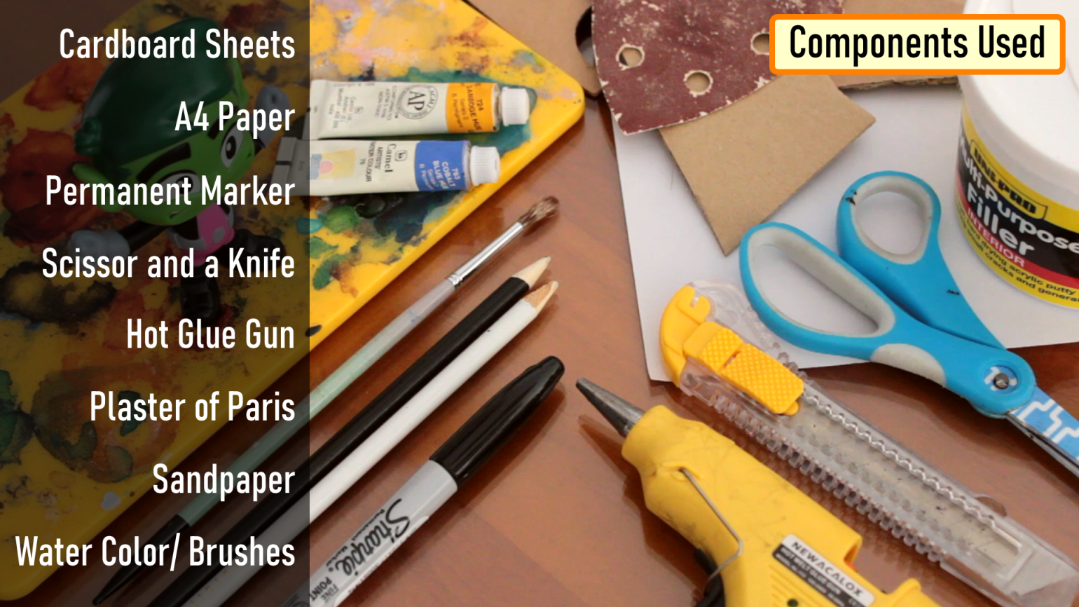
Components Used [Helmet Creation]
Printing
From Instructables, I printed out the two PDF templates on A4 paper.
Next, I extracted the shapes from the A4-sheet using a paper cutting scissor.
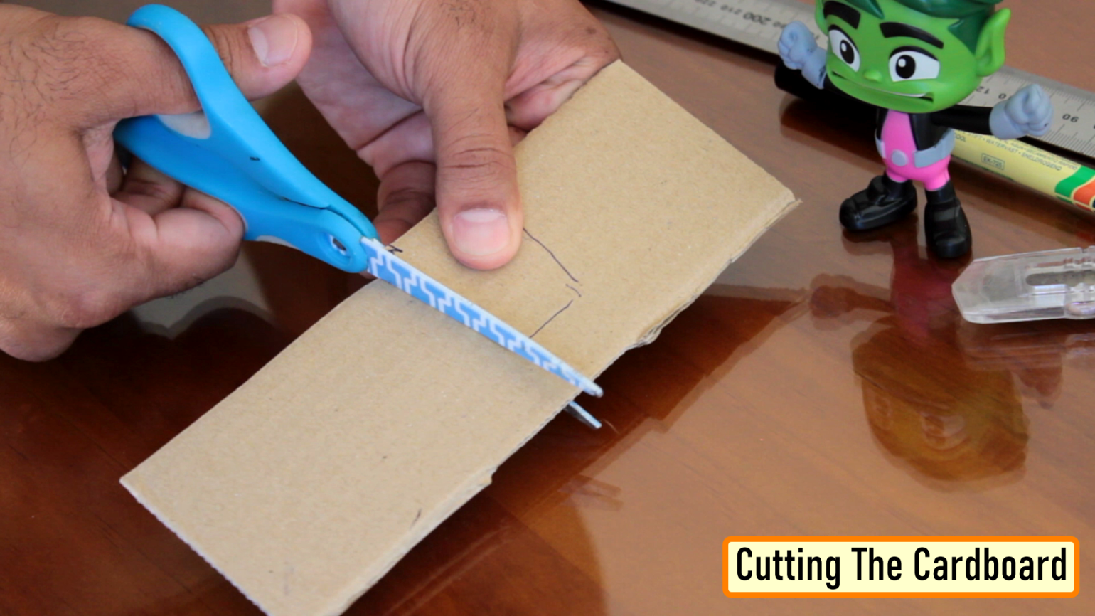
Cutting The Cardboard
Then I traced the paper-cutouts on pieces of cardboard and using both scissor and knife I extracted all the pieces of cardboard that I need for this helmet.
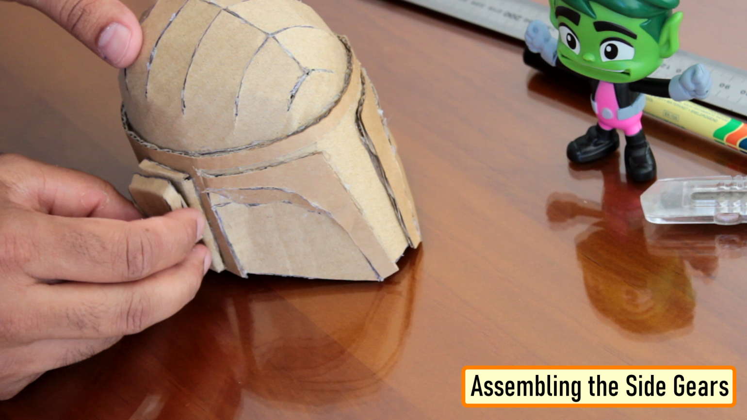
Assembling the Helmet
After that, using a hot-glue gun I joined all the cardboard cutouts.
Be very careful while using a hot-glue gun. Use gloves as much as possible to avoid the hot glue from burning your hand and fingers.
By using wood-glue instead of hot-glue you can get a cleaner and stronger finish, but hot glue is faster. Hot glue can also be more forgiving as you can re-heat and re-glue if you're unsatisfied with your seam. Please make sure you follow the exact sequence that I am showing in the video to avoid unnecessary re-heating and re-gluing of the cutouts.
Try applying the glue from the inner side as much as possible to leave the outer side neat and clean.
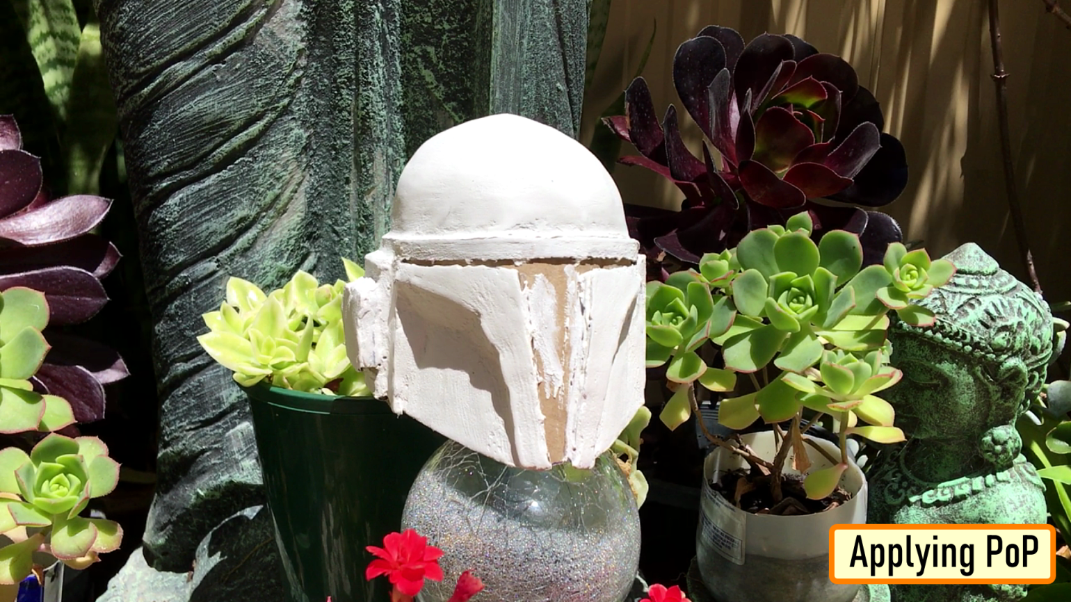
Then create a dense paste of Plaster-of-Paris. Apply some in each of the cracks and all around the helmet.
Apply multiple coats of PoP to get a nice and smooth texture.
Let it dry in bright sunlight.
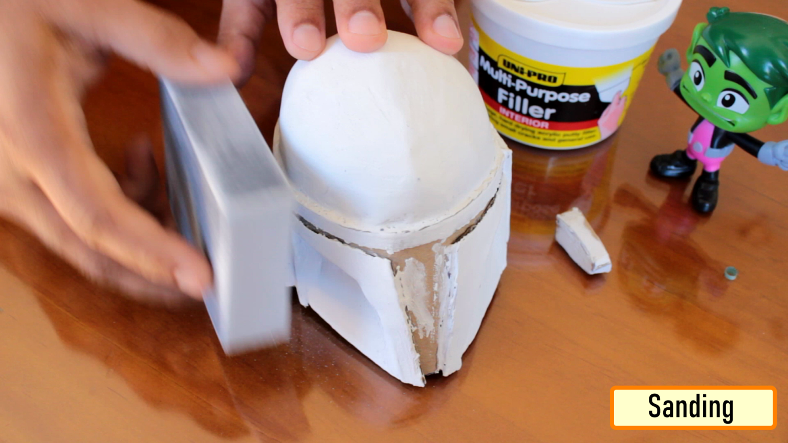
Take down all the rough edges using sandpaper. If you hit the cardboard, stop, you know you went a little too far. Frankly speaking, you don't need to make it super smooth as Boba Fett's helmet in reality is full of cracks and dents.
Cut the visor out after sanding and apply lots of coats of PoP.
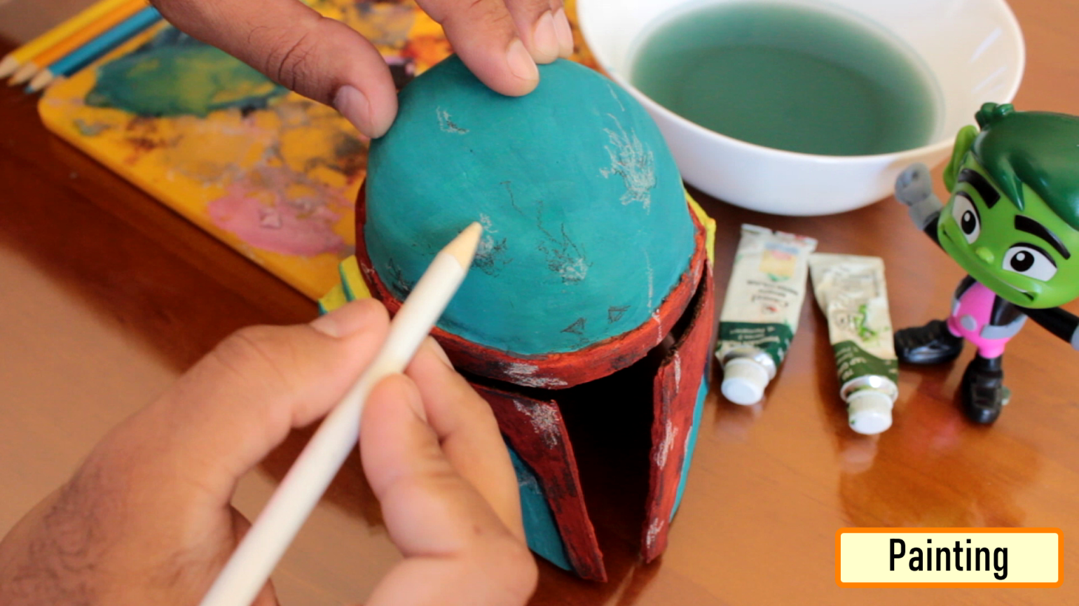
When you're happy with the finish, pick up your paintbrush and paint the helmet.
I used watercolor to paint the body of the helmet and pencil color to draw the cracks and fissures on it.
Make sure when applying watercolor don't use too much of water as that will make the PoP wet and the PoP will start mixing up with the color.
If you don't want to put the LED chaser in the helmet then you can stop this video right now. However, adding the LED chaser gives this helmet a sci-fi look.
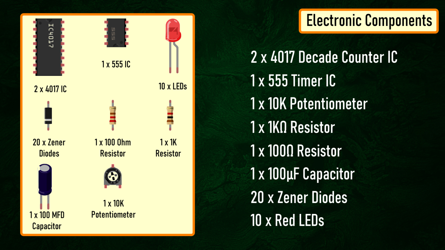
Components Used [Electronics]
The circuit is very simple.
The 555 Timer IC operates as a clock oscillator or clock generator. The output on PIN-3 goes high causing a shift.
The signal from the 555 IC clocks the 4017 decade counter. Output of 555 timer IC on PIN-3 is given as an input to 4017 IC through PIN-14. Whenever a pulse is received at theImage: signal-square-wave-01_ 1 clock input of IC 4017, the counter increments the count and activates the corresponding output PIN. This IC can count upto 10, so we have attached 10 LEDs to the circuit.
By increasing or decreasing the value of resistance of the 10K pot we can adjust the speed of the chaser circuit.
Since only one LED will be turned on at a given time, I have attached just one 220ohm current limiting resistor to the cluster of LEDs.
Now, to give the forward and reverse effect we are attaching another 4017 IC to this circuit. If lets say the 1st IC connects from 1 to 10 (left to right) then the second one should connect from 10 to 1 (right to left). However, now we cannot connect the counter ICs directly to the LEDs as we did before. We have to use Diodes to stop the reverse flow of current to the 2nd IC.
We have also lowered the value of the current limiting resistor to 100ohms as at a given time 2 LEDs will be on, one running from left and one from the right hand side.
So this is how my board looks like in 2D and 3D.
There are 3 breakout-boards in this 100cm x 100cm assembly.
Assembly
Title here
Lets start by soldering the Diodes to the board. Then, lets solder the 2 x Resistances to the board. After that, lets soldering the
100 MFD Capacitor to the board. Frankly speaking, using SMDs would have given the board a smaller an neater look.
Next, I am soldering the 3 x IC Bases to the board followed by plugging the ICs into them.
Now, lets solder the Potentiometer and the male pin header to the board.
And to conclude, lets solder the 10 x LEDs to the board. Solder the LEDs in a way that the look like an arch, so that they can fit inside the curved edge of the helmet.
Now let quickly test the chaser circuit before putting it inside the helmet. Ok, so I might lower the speed bit.. ahh... that looks perfect...
Thanks
Thanks again for checking my post. I hope it helps you.
If you want to support me subscribe to my YouTube Channel.
Gerber File
Measurements:
- PDF1
- PDF2
- BTC: 35ciN1Z49Y1bReX2U7Etd9hGPWzzzk8TzF
- DOGE: DDe7Fws24zf7acZevoT8uERnmisiHwR5st
- LTC: MQFkVkWimYngMwp5SMuSbMP4ADStjysstm
- ETH: 0x939aa4e13ecb4b46663c8017986abc0d204cde60
- BAT: 0x939aa4e13ecb4b46663c8017986abc0d204cde60
Thanks, see you again in my next tutorial.