How to make a portable data logger using an Arduino.
This project was made as part of my senior project at my university. The idea behind the device was to make a data logger that can be carried around a lab without the need to connect to a computer. In this segment, we will cover the components used for this project. Later, we'll get into calibrating the sensors, setting up software programs, and running some experiments.
System Overview
What Does It Measure?
The following table shows the parameters to be measured and the sensors used to measure them.
| S/N |
Measurement variable |
Sensor |
Range |
| 1 |
Temperature |
Thermocouple(K-type) |
-250°C-1250°C |
| 2 |
Mass |
Electronic load cell |
0 – 1 Kg |
| 3 |
Flow rate |
Hall Effect Flow meter |
1 – 30 Ltr/min |
The microcontroller is used to link all the components, get the digital data from all the ADCs, process them, and store them on the memory card. It also distributes power to all of the sensors.
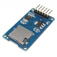
Arduino Micro SD Card Module
The communication between the microcontroller and the SD card uses SPI. The functions of the module are: Formatting and preparing the memory card, file naming, as well as opening and closing files.
The MAX6675 performs cold-junction compensation and digitizes the signal from a type-K thermocouple. The data is output in a 12-bit resolution. It resolves temperatures to 0.25°C, allows readings as high as +1024°C. The chip can also detect an open thermocouple.
By connecting the amplifier to the microcontroller, the changes in the resistance of the load cell can be read and with some calibration, very accurate weight measurements are obtained.
Sensors
Temperature Thermocouple
It is a K-type thermocouple with a Chromel {90% nickel and 10% chromium} Alumel {95% nickel, 2% manganese, 2% aluminium and 1% silicon} junction. It is has a temperature range of 0 to 800°C. It resistive to oxidation at higher temperatures but vulnerable to sulfur attacks.
The load cell used has two strain gauges. Strain (a planar resistor) deforms/stretches/contracts when the material of the load cells deforms appropriately. The limit for the strain gauge used is 5 Kg. Exceeding this limit will cause the load cell to deform permanently.
Flow sensor/Hall Effect Flow Meter
The Hall-effect flow sensor outputs approximately 4.5 pulses per second per liter/minute of flow. The pulses increase with an increase in the flow rate and the maximum flow rate is 30 L/min.
Integrating the Components
The integration of the system is done using the parts shown above. Integration is done first using simulation by Proteus Isis design suite for configuring and arranging the electronic components and developing a program that will be used for the device. The block diagram and schematic below show the general method used in the integration of the DAQ system.
Schematic is based on a design from The Engineering Projects
Next time, we will set the system up and run some experiments!