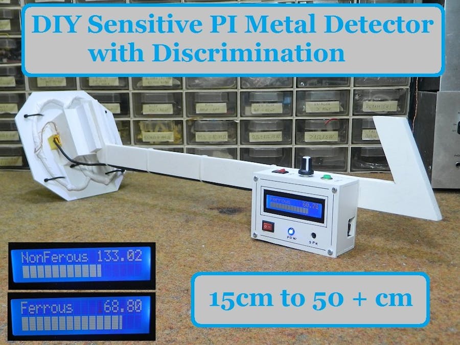
It can detect metal coin at 15cm +, and bigger metal objects at 50cm and more. Also capable of discriminating between ferrous and nonferrous
This time I will show you how to make a sensitive metal detector also capable of discriminating between ferrous and nonferrous materials. The sensitivity is satisfactory, given that it is a relatively simple device.
This project is sponsored by PCBgogo:
This is a continuation of David Crocker's project presented at the Arduino CC Forum in 2013. I decided to test its code because I did not find any evidence (Picture or video) that this metal detector was made by anyone and works well.
First I made a basic version with the code presented on GitHub, to make sure of the functionality of the device and then I upgraded the code so that it has an audible signal, and on a 16 on 2 LCD display visual information about the type of object detected (Ferrous or nonferrous material) and LCD bar graph for the proximity of detected objects.
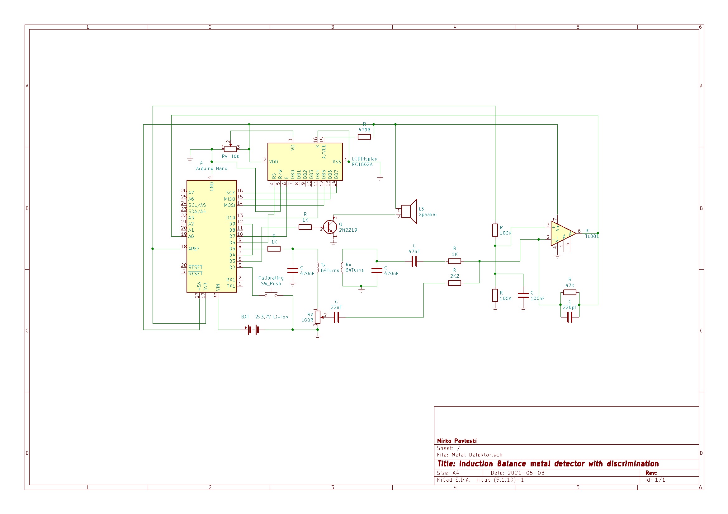
The device is very simple to build and consist of only a few components:
- Arduino nano microcontroller
- Operational amplifier (in my case LT1677, but you can use TL081 or 741 )
- Few resistors and capacitors
- Small transistor and speaker
This is a VLF (very low frequency) Induction Balance detector technology and contains two identical coils : transmitter and receiver coil. As with all induction balance detectors, coil balance is very critical. The potentiometer is used to zero the small 90 degrees out-of-phase component of the signal. (the in-phase component is nulled by adjusting the relative placement of the coils in typical IB-detector style). Each of the coils is wound on 11cm body using 64 turns of 0.5mm^2 enameled copper wire in a D shape, wrapped tape around them, screened them using aluminum foil bound with tinned copper wire (taking care to leave a small gap so that the screen doesn’t behave like a shorted turn), and tie-wrapped them on to a plastic plate.
We first need to determine the parallel resonant frequency of the primary coil-capacitor circuit using one of the many online calculators. I measured it with an oscilloscope, but if you adhere to the dimensions given above, it will be exactly 7.64 kHz, so you can directly enter the value given in the code. In the case of another value of the resonant frequency, we need to make an appropriate change in the code in the queue:
#define TIMER1_TOP (249) // fine-tune the frequency
As you can see in the video, the results are surprisingly good. Without the presence of a metal, device is perfectly stable. The range is relatively large and for example, a metal cover with a diameter of 15 cm is detected at a distance of more than 30 cm. Larger metal objects are detected at distances greater than 40-50cm. We can detect a small coin at a distance of 15cm in the air. I use two lithium batteries for the power supply which are connected in series (7.4 volts) and this voltage is connected to the Vin input of the Arduino. Consumption does not exceed 20mA so batteries last a very long time. The video describes in detail the construction of the entire device.
These are only preliminary results. There is a possibility to significantly improve the sensitivity by inserting a power MOSFET transistor for driving the Tx coil, but I will test and present it in one of the following videos.
// Induction balance metal detector

// We run the CPU at 16MHz and the ADC clock at 1MHz. ADC resolution is reduced to 8 bits at this speed.

// Timer 1 is used to divide the system clock by about 256 to produce a 62.5kHz square wave.
// This is used to drive timer 0 and also to trigger ADC conversions.
// Timer 0 is used to divide the output of timer 1 by 8, giving a 7.8125kHz signal for driving the transmit coil.
// This gives us 16 ADC clock cycles for each ADC conversion (it actually takes 13.5 cycles), and we take 8 samples per cycle of the coil drive voltage.
// The ADC implements four phase-sensitive detectors at 45 degree intervals. Using 4 instead of just 2 allows us to cancel the third harmonic of the
// coil frequency.

// Timer 2 will be used to generate a tone for the earpiece or headset.

// Other division ratios for timer 1 are possible, from about 235 upwards.

// Wiring:
// Connect digital pin 4 (alias T0) to digital pin 9
// Connect digital pin 5 through resistor to primary coil and tuning capacitor
// Connect output from receive amplifier to analog pin 0. Output of receive amplifier should be biased to about half of the analog reference.
// When using USB power, change analog reference to the 3.3V pin, because there is too much noise on the +5V rail to get good sensitivity.
#include <LiquidCrystal.h>
#include <LcdBarGraph.h>
#define max_ampAverage 200
LiquidCrystal lcd(6, 7, 10, 11, 12, 13);
LcdBarGraph lbg(&lcd, 16, 0, 1);

#define TIMER1_TOP  (259)        // can adjust this to fine-tune the frequency to get the coil tuned (see above)

#define USE_3V3_AREF  (1)        // set to 1 of running on an Arduino with USB power, 0 for an embedded atmega28p with no 3.3V supply available

// Digital pin definitions
// Digital pin 0 not used, however if we are using the serial port for debugging then it's serial input
const int debugTxPin = 1;        // transmit pin reserved for debugging
const int encoderButtonPin = 2;  // encoder button, also IN0 for waking up from sleep mode
const int earpiecePin = 3;       // earpiece, aka OCR2B for tone generation
const int T0InputPin = 4;
const int coilDrivePin = 5;
const int LcdRsPin = 6;
const int LcdEnPin = 7;
const int LcdPowerPin = 8;       // LCD power and backlight enable
const int T0OutputPin = 9;
const int lcdD4Pin = 10;
const int lcdD5Pin = 11;         // pins 11-13 also used for ICSP
const int LcdD6Pin = 12;
const int LcdD7Pin = 13;

// Analog pin definitions
const int receiverInputPin = 0;
const int encoderAPin = A1;
const int encoderBpin = A2;
// Analog pins 3-5 not used

// Variables used only by the ISR
int16_t bins[4];                 // bins used to accumulate ADC readings, one for each of the 4 phases
uint16_t numSamples = 0;
const uint16_t numSamplesToAverage = 1024;

// Variables used by the ISR and outside it
volatile int16_t averages[4];    // when we've accumulated enough readings in the bins, the ISR copies them to here and starts again
volatile uint32_t ticks = 0;     // system tick counter for timekeeping
volatile bool sampleReady = false;  // indicates that the averages array has been updated

// Variables used only outside the ISR
int16_t calib[4];                // values (set during calibration) that we subtract from the averages

volatile uint8_t lastctr;
volatile uint16_t misses = 0;    // this counts how many times the ISR has been executed too late. Should remain at zero if everything is working properly.

const double halfRoot2 = sqrt(0.5);
const double quarterPi = 3.1415927/4.0;
const double radiansToDegrees = 180.0/3.1415927;

// The ADC sample and hold occurs 2 ADC clocks (= 32 system clocks) after the timer 1 overflow flag is set.
// This introduces a slight phase error, which we adjust for in the calculations.
const float phaseAdjust = (45.0 * 32.0)/(float)(TIMER1_TOP + 1);

float threshold = 5.0;          // lower = greater sensitivity. 10 is just about usable with a well-balanced coil.
                                 // The user will be able to adjust this via a pot or rotary encoder.

void setup()
{
  lcd.begin(16, 2);// LCD 16X2
  pinMode(encoderButtonPin, INPUT_PULLUP);
  digitalWrite(T0OutputPin, LOW);
  pinMode(T0OutputPin, OUTPUT);       // pulse pin from timer 1 used to feed timer 0
  digitalWrite(coilDrivePin, LOW);
  pinMode(coilDrivePin, OUTPUT);      // timer 0 output, square wave to drive transmit coil

  cli();
  // Stop timer 0 which was set up by the Arduino core
  TCCR0B = 0;        // stop the timer
  TIMSK0 = 0;        // disable interrupt
  TIFR0 = 0x07;      // clear any pending interrupt

  // Set up ADC to trigger and read channel 0 on timer 1 overflow
#if USE_3V3_AREF
  ADMUX = (1 << ADLAR);                   // use AREF pin (connected to 3.3V) as voltage reference, read pin A0, left-adjust result
#else
  ADMUX = (1 << REFS0) | (1 << ADLAR);    // use Avcc as voltage reference, read pin A0, left-adjust result
#endif
  ADCSRB = (1 << ADTS2) | (1 << ADTS1);   // auto-trigger ADC on timer/counter 1 overflow
  ADCSRA = (1 << ADEN) | (1 << ADSC) | (1 << ADATE) | (1 << ADPS2);  // enable adc, enable auto-trigger, prescaler = 16 (1MHz ADC clock)
  DIDR0 = 1;

  // Set up timer 1.
  // Prescaler = 1, phase correct PWM mode, TOP = ICR1A
  TCCR1A = (1 << COM1A1) | (1 << WGM11);
  TCCR1B = (1 << WGM12) | (1 << WGM13) | (1 << CS10);    // CTC mode, prescaler = 1
  TCCR1C = 0;
  OCR1AH = (TIMER1_TOP/2 >> 8);
  OCR1AL = (TIMER1_TOP/2 & 0xFF);
  ICR1H = (TIMER1_TOP >> 8);
  ICR1L = (TIMER1_TOP & 0xFF);
  TCNT1H = 0;
  TCNT1L = 0;
  TIFR1 = 0x07;      // clear any pending interrupt
  TIMSK1 = (1 << TOIE1);

  // Set up timer 0
  // Clock source = T0, fast PWM mode, TOP (OCR0A) = 7, PWM output on OC0B
  TCCR0A = (1 << COM0B1) | (1 << WGM01) | (1 << WGM00);
  TCCR0B = (1 << CS00) | (1 << CS01) | (1 << CS02) | (1 << WGM02);
  OCR0A = 7;
  OCR0B = 3;
  TCNT0 = 0;
  sei();

  while (!sampleReady) {}    // discard the first sample
  misses = 0;
  sampleReady = false;

  Serial.begin(19200);
}

// Timer 0 overflow interrupt. This serves 2 purposes:
// 1. It clears the timer 0 overflow flag. If we don't do this, the ADC will not see any more Timer 0 overflows and we will not get any more conversions.
// 2. It increments the tick counter, allowing is to do timekeeping. We get 62500 ticks/second.
// We now read the ADC in the timer interrupt routine instead of having a separate comversion complete interrupt.
ISR(TIMER1_OVF_vect)
{
  ++ticks;
  uint8_t ctr = TCNT0;
  int16_t val = (int16_t)(uint16_t)ADCH;    // only need to read most significant 8 bits
  if (ctr != ((lastctr + 1) & 7))
  {
    ++misses;
  }
  lastctr = ctr;
  int16_t *p = &bins[ctr & 3];
  if (ctr < 4)
  {
    *p += (val);
    if (*p > 15000) *p = 15000;
  }
  else
  {
    *p -= val;
    if (*p < -15000) *p = -15000;
  }
  if (ctr == 7)
  {
    ++numSamples;
    if (numSamples == numSamplesToAverage)
    {
      numSamples = 0;
      if (!sampleReady)      // if previous sample has been consumed
      {
        memcpy((void*)averages, bins, sizeof(averages));
        sampleReady = true;
      }
      memset(bins, 0, sizeof(bins));
    }
  }
}

void loop()
{
  while (!sampleReady) {}
  uint32_t oldTicks = ticks;

  if (digitalRead(encoderButtonPin) == LOW)
  {
    // Calibrate button pressed. We save the current phase detector outputs and subtract them from future results.
    // This lets us use the detector if the coil is slightly off-balance.
    // It would be better to everage several samples instead of taking just one.
    for (int i = 0; i < 4; ++i)
    {
      calib[i] = averages[i];
    }
    sampleReady = false;
    Serial.print("Calibrated: ");

    lcd.setCursor(0,0);
    lcd.print("Calibrating...  ");
    for (int i = 0; i < 4; ++i)
    {
      Serial.write(' ');

      Serial.print(calib[i]);

    lcd.setCursor(0,1);
    lcd.print(' ');
    lcd.print(calib[4]);
    lcd.print("        ");
    }
    Serial.println();
  }
  else
  {
    for (int i = 0; i < 4; ++i)
    {
      averages[i] -= calib[i];
    }
    const double f = 200.0;

    // Massage the results to eliminate sensitivity to the 3rd harmonic, and divide by 200
    double bin0 = (averages[0] + halfRoot2 * (averages[1] - averages[3]))/f;
    double bin1 = (averages[1] + halfRoot2 * (averages[0] + averages[2]))/f;
    double bin2 = (averages[2] + halfRoot2 * (averages[1] + averages[3]))/f;
    double bin3 = (averages[3] + halfRoot2 * (averages[2] - averages[0]))/f;
    sampleReady = false;          // we've finished reading the averages, so the ISR is free to overwrite them again

    double amp1 = sqrt((bin0 * bin0) + (bin2 * bin2));
    double amp2 = sqrt((bin1 * bin1) + (bin3 * bin3));
    double ampAverage = (amp1 + amp2)/2.0;

    // The ADC sample/hold takes place 2 clocks after the timer overflow
    double phase1 = atan2(bin0, bin2) * radiansToDegrees + 45.0;
    double phase2 = atan2(bin1, bin3) * radiansToDegrees;

    if (phase1 > phase2)
    {
      double temp = phase1;
      phase1 = phase2;
      phase2 = temp;
    }

    double phaseAverage = ((phase1 + phase2)/2.0) - phaseAdjust;
    if (phase2 - phase1 > 180.0)
    {
      if (phaseAverage < 0.0)
      {
        phaseAverage += 180.0;
      }
      else
      {
        phaseAverage -= 180.0;
      }
    }

    // For diagnostic purposes, print the individual bin counts and the 2 indepedently-calculated gains and phases
    Serial.print(misses);
    Serial.write(' ');

    if (bin0 >= 0.0) Serial.write(' ');
    Serial.print(bin0, 2);
    Serial.write(' ');
    if (bin1 >= 0.0) Serial.write(' ');
    Serial.print(bin1, 2);
    Serial.write(' ');
    if (bin2 >= 0.0) Serial.write(' ');
    Serial.print(bin2, 2);
    Serial.write(' ');
    if (bin3 >= 0.0) Serial.write(' ');
    Serial.print(bin3, 2);
    Serial.print("    ");
    Serial.print(amp1, 2);
    Serial.write(' ');
    Serial.print(amp2, 2);
    Serial.write(' ');
    if (phase1 >= 0.0) Serial.write(' ');
    Serial.print(phase1, 2);
    Serial.write(' ');
    if (phase2 >= 0.0) Serial.write(' ');
    Serial.print(phase2, 2);
    Serial.print("    ");

    // Print the final amplitude and phase, which we use to decide what (if anything) we have found)
    if (ampAverage >= 0.0) Serial.write(' ');
    Serial.print(ampAverage, 1);
    Serial.write(' ');

        lcd.setCursor(0,0);
        lcd.print("          ");
        lcd.print(ampAverage);
        lcd.setCursor(0,1);
        lbg.drawValue(ampAverage, max_ampAverage);

    if (phaseAverage >= 0.0) Serial.write(' ');
    Serial.print((int)phaseAverage);

    // Decide what we have found and tell the user
    if (ampAverage >= threshold)
    {
      // When held in line with the centre of the coil:
      // - non-ferrous metals give a negative phase shift, e.g. -90deg for thick copper or aluminium, a copper olive, -30deg for thin alumimium.
      // Ferrous metals give zero phase shift or a small positive phase shift.
      // So we'll say that anything with a phase shift below -20deg is non-ferrous.
      if (phaseAverage < -20.0)
      {
        Serial.print(" Non-ferrous");
        lcd.setCursor(0,0);
        lcd.print("NonFerous ");

      }
      else
      {
        Serial.print(" Ferrous");
        lcd.setCursor(0,0);
        lcd.print("Ferrous    ");
      }
      float temp = ampAverage;

       int thisPitch = map (temp, 10, 200, 100, 1500);
       tone(3, thisPitch,120);

      while (temp > threshold)
      {
        Serial.write('!');
        temp -= (threshold/2);
      }
    }
    Serial.println();

   }
  while (ticks - oldTicks < 8000)
  {
  }
}