In this tutorial, we will build a simple yet highly effective Smart Security Alarm System using an Arduino, a Passive Infrared (PIR) Motion Sensor, and a buzzer. This project is perfect for beginners who want to get hands-on experience with hardware interrupts, sensor calibration, and basic automation.
Project Overview
This system monitors a designated area for any human or animal movement. When motion is detected, the PIR sensor triggers the microcontroller, which instantly sounds an alarm and flashes an LED indicator.
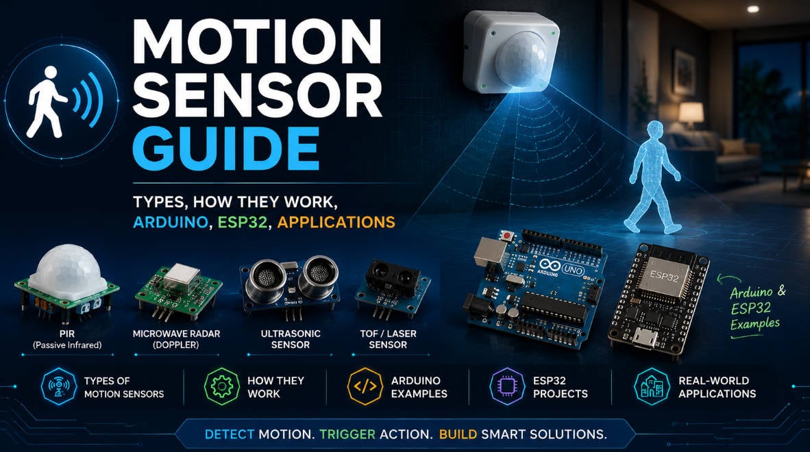
Before we dive into the build, it is important to understand how these sensors detect movement. If you are new to this technology, you can check out this comprehensive motion sensor guide to learn about the differences between PIR, microwave, and ultrasonic motion sensors, as well as their common applications.
Components Required
To build this project, you will need the following components:
Hardware Connection (Schematic)
The wiring for this project is straightforward. Connect the components to your Arduino as follows:
- PIR Sensor:
- VCC ➡️ Arduino 5V
- GND ➡️ Arduino GND
- OUT (Signal) ➡️ Arduino Digital Pin 2 (We use Pin 2 because it supports external interrupts on the Arduino Uno).
- Buzzer:
- Positive (+) ➡️ Arduino Digital Pin 8
- Negative (-) ➡️ Arduino GND
- LED:
- Anode (Long leg) ➡️ 220Ω Resistor ➡️ Arduino Digital Pin 13
- Cathode (Short leg) ➡️ Arduino GND
The Code
Upload the following sketch to your Arduino board. This code utilizes an interrupt service routine (ISR) to ensure the microcontroller responds instantly the moment motion is detected, without being slowed down by delay() functions in the main loop.
// Pin Definitions
const int PIR_PIN = 2;    // PIR sensor output connected to Pin 2 (Interrupt 0)
const int BUZZER_PIN = 8; // Buzzer connected to Pin 8
const int LED_PIN = 13;   // LED connected to Pin 13

// Volatile variable for Interrupt Service Routine (ISR)
volatile bool motionDetected = false;

void setup() {
  pinMode(PIR_PIN, INPUT);
  pinMode(BUZZER_PIN, OUTPUT);
  pinMode(LED_PIN, OUTPUT);

  Serial.begin(9600);
  Serial.println("Calibrating PIR sensor... Please wait.");

  // Give the PIR sensor some time to stabilize (typically 10-60 seconds)
  delay(20000);
  Serial.println("Sensor Active. Monitoring area...");

  // Attach external interrupt to Pin 2. Trigger on RISING edge (when motion starts)
  attachInterrupt(digitalPinToInterrupt(PIR_PIN), motionDetectedISR, RISING);
}

void loop() {
  if (motionDetected) {
    Serial.println("⚠️ MOTION DETECTED! Triggering Alarm!");

    // Sound the alarm and flash the LED
    for (int i = 0; i < 5; i++) {
      digitalWrite(LED_PIN, HIGH);
      tone(BUZZER_PIN, 1000); // 1KHz sound
      delay(300);

      digitalWrite(LED_PIN, LOW);
      noTone(BUZZER_PIN);
      delay(300);
    }

    // Reset the flag
    motionDetected = false;
    Serial.println("System reset. Monitoring area...");
  }
}

// Interrupt Service Routine
void motionDetectedISR() {
  motionDetected = true;
}
Calibration and Testing
Once the code is uploaded, follow these steps to test your system:
- Warm-up Phase: When you power on the Arduino, the PIR sensor needs about 20 seconds to calibrate to the ambient infrared signature of the room. Keep still during this time.
- Sensitivity and Delay Adjustments: On the HC-SR501 physical board, there are two orange potentiometers.
- Sensitivity (Sx): Turn clockwise to increase the detection range (up to 7 meters).
- Time Delay (Tx): Turn counter-clockwise to minimize the delay (about 3 seconds) for quick testing.
- Triggering the Alarm: Walk in front of the sensor. The serial monitor should print
"MOTION DETECTED!", the red LED will flash, and the buzzer will emit a pulsing alarm sound.
Conclusion
You have successfully built a DIY Smart Security Alarm System! This basic setup can easily be expanded. For example, you could replace the buzzer with an ESP8266 Wi-Fi module to send push notifications to your smartphone when motion is detected.
If you want to explore more about how different types of sensors operate or choose the right sensor for your next project, don't forget to review the motion sensor guide we referenced earlier.
Happy making!